Phase Relation in Pure Inductive Circuit:
Phase Relation in Pure Inductive Circuit – As discussed already, the voltage current relation in the case of an inductor is given by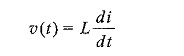
Consider the function i(t) = Im sin ωt = Im [ Imejωt ] or Im∠0°
where
Vm = ωL Im = XLIm
ej90° = j = 1 ∠90°
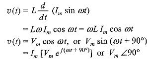
If we draw the waveforms for both, voltage and current, as shown in Fig. 4.19, we can observe the phase difference between these two waveforms.
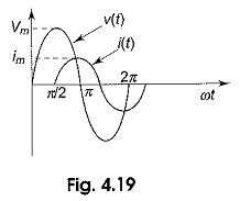
As a result, in a pure inductor the voltage and current are out of phase. The current lags behind the voltage by 90° in a pure inductor as shown in Fig. 4.20.
The impedance which is the ratio of exponential voltage to the corresponding current, is given by
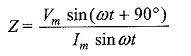
where
Vm = ωL Im
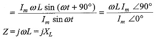
where XL = ωL and is called the inductive reactance.
Hence, a pure inductor has an impedance whose value is ωL.
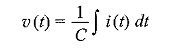
Phase Relation in Pure Capacitor:
As discussed already, the relation between voltage and current is given by
Consider the function i(t) = Im sin ωt = Im [ Imejωt ] or Im∠0°
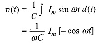
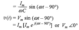
where
Vm = Im/ωC
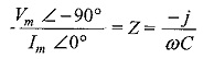
Hence, the impedance is Z = -j/ωC = -jXC
Where XC = 1/ωC and is called the capacitive reactance.
If we draw the waveform for both, voltage and current, as shown in Fig. 4.21, there is a phase difference between these two waveforms..
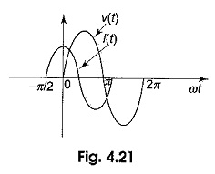
As a result, in a pure capacitor, the current leads the voltage by 90°. The impedance value of a pure capacitor
![]()