Armature Reaction in DC Machine:
When the armature of a dc machine carries current, the distributed armature winding produces its own mmf (distributed) known as armature reaction in DC Machine. The machine air-gap is now acted upon by the resultant mmf distribution caused by simultaneous action of the field ampere-turns (ATf) and armature ampere-turns (ATa). As a result the air-gap flux density gets distorted as compared to the flat-topped (trapezoidal) wave with quarter-wave symmetry when the armature did not carry any current.
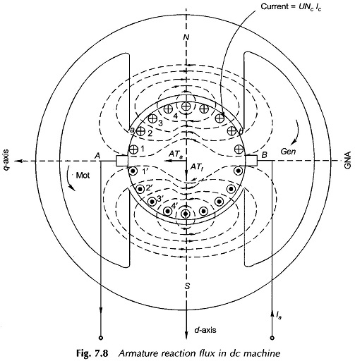
Figure 7.8 shows the cross-sectional view of a 2-pole machine with single equivalent conductor in each slot (current/conductor = UNcIc where U = coil-sides/slot, Nc = conductors/coil-side (turns/coil) and Ic = conductor current). Two axes can be recognized—the axes of main poles called the direct axis (d-axis) and the axis at 90° to it called the quadrature axis (q-axis). Obviously the q-axis is the geometric neutral axis (GNA) of the machine. The brushes in a dc machine are normally located along the q-axis.
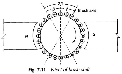
Because of commutator action, armature current distribution is as shown in Fig. 7.8 for a 2-pole machine (or Fig. 6.11 for a 4-pole machine). All the conductors on the armature periphery between adjacent brushes carry currents (of constant value, UNcIc) in one direction and the current distribution alternates along the periphery. This current pattern remains fixed in space independent of armature rotation. Since the brushes are placed along GNA, the stationary armature current pattern is congruent with the main poles. Also, the current pattern can be shifted by moving all the brushes simultaneously to either side; this is not a normal operation in a dc machine.
It is easy to see from Fig. 7.8 that the axis of ATa lies along the q-axis at 90° elect. to this axis of main poles which lies along the d-axis (ATa lags behind ATf with respect to the direction of armature rotation for the motoring mode and vice versa for the generating mode). It may be noticed that ATa and ATf as shown by arrows are not vectors as their space-angle distribution is non-sinusoidal (though periodic). Armature Reaction in DC Machine with axis at 90° to the main field axis is known as cross-magnetizing mmf. Figure 7.8 also shows the flux pattern, in dotted lines, caused by armature reaction acting alone. It is immediately observed that the armature reaction flux strengthens each main pole at one end and weakens it at the other end (cross-magnetizing effect). If the iron in the magnetic circuit is assumed unsaturated (therefore linear), the net flux/pole remains unaffected by armature reaction though the air-gap flux density distribution gets distorted. If the main pole excitation is such that iron is in the saturated region of magnetization (this is the case in a practical machine), the increase in flux density at one end of the poles caused by armature reaction is less than the decrease at the other end, so that there is a net reduction in the flux/pole, a demagnetizing effect; the decrement being dependent upon the state of magnetization of iron and the amount of ATa (i.e. the armature current).
It may be summarized here that the nature of Armature Reaction in DC Machine is cross-magnetizing with its axis (stationary) along the q-axis (at 90° elect. to the main pole axis). It causes no change in flux/pole if the iron is unsaturated but causes reduction in flux/pole (demagnetizing effect) in presence of iron saturation.
Graphical Picture of Flux Density Distribution:
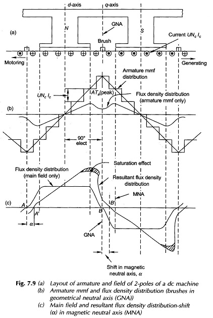
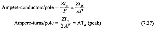
For a better understanding of the interaction between the field and the armature magnetic field, consider the developed diagram of Fig. 7.9(a) for one pole-pair with brushes placed in geometrical neutral axis (GNA), which is also magnetic neutral axis (MNA) when armature is not carrying current. Using the principles as we know, the armature mmf distribution is drawn in Fig. 7.9(b) which is a stepped wave with axis shift of 90° elect. from the main pole axis (d-axis), i.e. it is cross-magnetizing. Each step of the wave has a height of UNcIc where U= coil-sides/slot, Nc = conductors/coil-side (turns/coil) and lc, = conductor current. The stepped-wave of mmf can be well approximated as a triangular wave as shown in Fig. 7.9(b). The peak value of armature ampere-turns is obtained as follows:
The exact way to find the flux density owing to the simultaneous action of field and armature ampere-turns is to find the resultant ampere-turn distribution
![]()
where θ is electrical space angle.
A simpler procedure, however, will be adopted by assuming linearity of the magnetic circuit making possible the superposition of individual flux density waves to obtain the resultant flux density as illustrated in Fig. 7.9(c).
The flux density of ATa(θ) is shown in Fig. 7.9(b) which, because of large air-gap in the interpolar region, has a strong dip along the q-axis even though ATa (peak) is oriented along it. The flux density of the main field alone (trapezoidal wave) and the resultant flux density are both drawn in Fig. 7.9(c). It is found from this figure that the armature reaction mmf causes the flux density wave to get distored so as to be depressed in one half of the pole and causes it to be strengthened equally (linearity effect) in the other half (cross-magnetizing effect) because of the odd symmetry with respect to the d-axis of the flux density wave of the armature mmf. It is, therefore, seen that while the resultant flux density wave is distorted, the flux/pole remains unchanged at its value in the absence of the armature current. Figure 7.9(c) also reveals that apart from distortion of the resultant flux density wave, its MNA also gets shifted from its GNA by a small angle α so that the brushes placed in GNA are no longer in MNA as is the case in the absence of armature current. This effect is countered by interpoles placed in GNA.
The effect of iron saturation can now be brought into picture. At angle θ on either side of the d-axis, ampere-turn acting on elemental magnetic path are (ATf ± ATa). It is found from the magnetization curve of Fig. 7.10 that the increase in flux density on one side of the d-axis caused by additive ATa is less than the decrease in flux density on the other side by subtractive ATa.
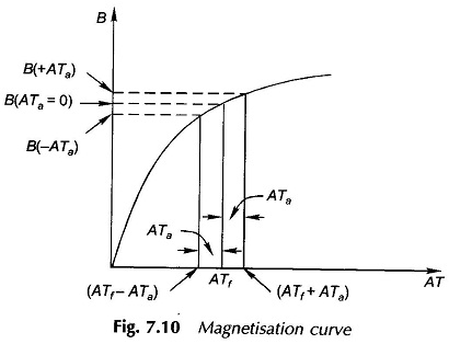
As a consequence in presence of saturation, armature reaction apart from being cross-magnetizing also causes a net reduction in flux/pole, a demagnetizing effect. However, no simple quantitative relationship can be established between demagnetization and ATf and ATa. The reduction in the resultant flux density caused by saturation of iron is shown by the cross-hatched areas in Fig. 7.9(c).
To summarize, the Armature Reaction in DC Machine is cross-magnetizing causing distortion in the flux density wave shape and a slight shift in MNA. It also causes demagnetization because a machine is normally designed with iron slightly saturated.
Distortion of flux density distribution resulting in increase of flux density on one side of the pole and decrease on the other, causes iron-loss in teeth to increase because these depend upon the square of the flux density (approximately). Distortion of flux distribution also has an adverse effect on commutation but this is overcome by interpoles. This distortion, in fact, is an important factor limiting the short-time overloading capacity of a dc machine.
The cross-magnetizing effect of the armature reaction can be reduced by making the main field ampere-turns larger compared to the armature ampere-turns such that the main field mmf exerts predominant control over the air-gap flux. This is achieved by:
- Introducing saturation in the teeth and pole-shoe.
- By chamfering the pole-shoes which increases the air-gap at the pole tips. This method increases the reluctance to the path of main flux but its influence on the cross-flux is much greater.
- The best yet the most expensive method is to compensate the armature reaction mmf by a compensating winding located in the pole-shoes and carrying a suitable current.