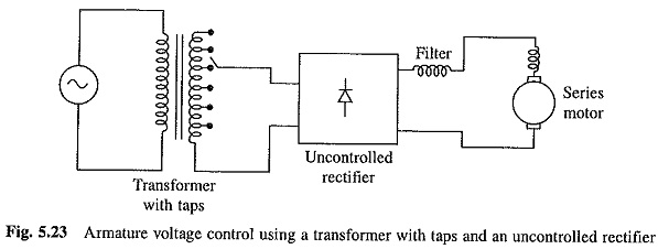
Armature Voltage Control using Transformer:
Variable voltage for the dc motor control can also be obtained by either using an auto-transformer or a Armature Voltage Control using Transformer with tappings (either on primary or on secondary) followed by an uncontrolled rectifier as shown in Fig. 5.23. A reactor is connected in the armature circuit to improve armature current waveform.
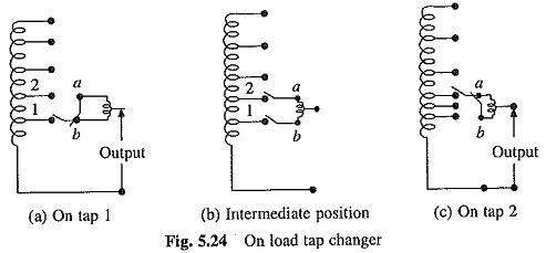
Auto-transformer can be employed only for low power ratings. For high power applications a transformer with tappings is employed and tap changing is done with the help of an on load tap changer (Fig. 5.24) to avoid severe voltage transients, produced due to interruption of current in open circuit transition.
A mid-point auto-transformer is used to carry out on load tap changing. When on tap position 1, both the terminals of auto-transformer are connected together. For changing to tap 2, terminal ‘a’ is first connected to tap 2. Terminal is now disconnected from tap 1 and connected to ‘a’.
This scheme is employed in 25 kV single phase 50 Hz ac traction.
The important features of Armature Voltage Control using Transformer scheme are:
(a) Output voltage can be changed only in steps;
(b) Rectifier output voltage waveform does not change as the output voltage in reduced. A good power factor is maintained at the source and current harmonics introduced in the supply lines do not increase abnormally, like in the case of a controlled rectifier when motor voltage is reduced to a small value; and
(c) Because of the use of diode bridge, circuit is not capable of regeneration.