Capacitance Voltage Transformer:
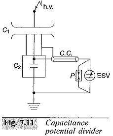
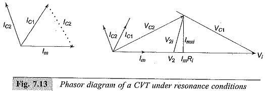
The errors due to harmonic voltages can be eliminated by the use of capacitive voltage dividers with an electrostatic voltmeter or a high impedance meter such as a T.V.M. If the meter is connected through a long cable, its capacitance has to be taken into account in calibration. Usually, a standard compressed air or gas capacitor is used as C1 (Fig. 7.11), and C2 may be any large capacitor and to C2 through a shielded cable, and C2 is completely shielded in a box to avoid stray Capacitance Voltage Transformer. The applied voltage V1 is given by
where
C1 – Standard compressed gas h.v. capacitor
C2 – Standard low voltage capacitor
ESV – Electrostatic voltmeter
P – Protective gap
C.C. – Connecting cable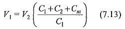 where Cm is the Capacitance Voltage Transformer of the meter and the connecting cable and the leads and V2 is the meter reading.
Capacitance divider with a suitable matching or isolating potential transformer tuned for resonance condition is often used in power systems for voltage measurements. This is often referred to as CVT. In contrast to simple capacitance divider which requires a high impedance meter like a T.V.M. or an electrostatic, voltmeter, a CVT can be connected to a low impedance device like a wattmeter pressure coil or a relay coil. CVT can supply a load of a few VA. The schematic diagram of a CVT with its equivalent circuit is given in Fig. 7.12. C1 is made of a few units of high voltage capacitors, and the total Capacitance Voltage Transformer will be around a few thousand picofarads as against a gas filled standard capacitor of about 100 pF.
A matching transformer is connected between the load or meter M and C2. The transformer ratio is chosen on economic grounds, and the h.v. winding rating may be 10 to 30 kV with the I.v. winding rated from 100 to 500 V. The value of the tuning choke L is chosen to make the equivalent circuit of the CVT purely resistive or to bring resonance condition. This condition is satisfied when
![]()
where,
L= inductance of the choke, and
LT= equivalent inductance of the transformer referred to h.v. side.
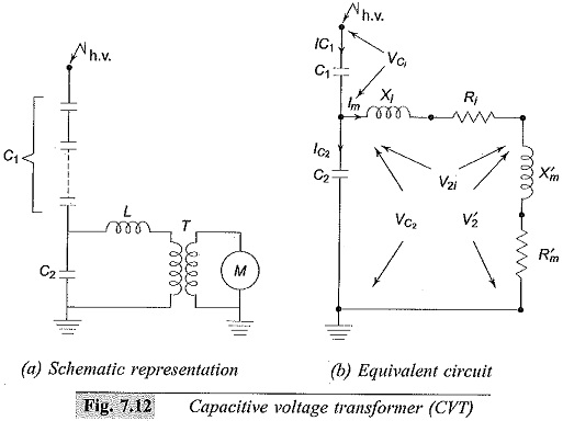
The phasor diagram of the CVT under resonant conditions is shown in Fig. 7.13. The meter reactance, Xm is neglected and is taken as a resistance load Rm when the load is connected to the voltage divider side. The voltage across the potential transformer V2 = Im.Rm and the voltage across the capacitor VC2 = V2 + Im (Re + j Xe). The Phasor diagram is written taking V1 as the reference phasor
It is can be seen resistance and reactance are not shown separately and are included in Ri and Xi, the resistance and reactance of tuning inductor L.
The Voltage ratio,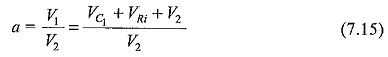
Neglecting the reactance drop ImXe, VRi is the voltage drop across the tuning inductor and the transformer resistance. The voltage V2 (meter voltage) will be in phase with the input voltage V1.
The advantages of a CVT are:
- simple design and easy installation,
- can be used both as a voltage measuring device for meter and relaying purposes and also as a coupling condenser for power line carrier communication and relaying.
- frequency independent voltage distribution along elements as against conventional magnetic potential transformers which require additional insulation design against surges, and
- provides isolation between the high voltage terminal and low voltage
The disadvantages of a CVT are:
- the voltage ratio is susceptible to temperature variation and
- the problem Of inducing ferro-resonance in power systems.