Voltage Transformer Earthing:
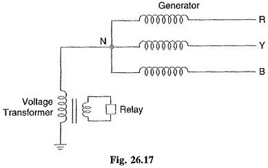
In this method of neutral earthing, the primary of a single-phase Voltage Transformer Earthing is connected between the neutral and the earth as shown in Fig. 26.17. A low resistor in series with a relay is connected across the secondary of the voltage transformer. The Voltage Transformer Earthing provides a high reactance in the neutral earthing circuit and operates virtually as an ungrounded neutral system. An earth fault on any phase produces a voltage across the relay. This causes the operation of the protective device.
The following are the advantages of voltage transformer earthing :
- The transient overvoltages on the system due to switching and arcing grounds are reduced. It is because voltage transformer provides high reactance to the earth path.
- This type of earthing has all the advantages of ungrounded neutral system.
- Arcing grounds are eliminated.
The following are the disadvantages of voltage transformer earthing :
- When earth fault occurs on any phase, the line voltage appears across line to earth capaci The system insulation will be overstressed.
- The earthed neutral acts as a reflection point for the travelling waves through the machine This may result in high voltage build up.
Applications:
The use of this system of neutral earthing is normally confined to generator equipments which are directly connected to step-up power transformers.
Grounding Transformer:
We sometimes have to create a neutral point on a 3-phase, 3-wire system (e.g. delta connection etc.) to change it into 3-phase, 4-wire system. This can be done by means of a grounding transformer. It is a core type transformer having three limbs built in the same fashion as that of the power transformer. Each limb of the transformer has two identical windings wound deferentially (i.e. directions of current in the two windings on each limb are opposite to each other) as shown in Fig. 26.18. Under normal operating conditions, the total flux in each limb is negligibly small. Therefore, the transformer draws very small magnetizing current.
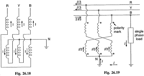
Fig. 26.19 shows the use of grounding transformer to create neutral point N. If we connect a single-phase load between one line and neutral, the load current I divides into three equal currents in each winding. Because the currents are equal, the neutral point stays fixed and the line to neutral voltages remain balanced as they would be on a regular 4-wire system. In practice, the single-phase loads are distributed as evenly as possible between the three phases and neutral so that unbalanced load current I is relatively small.
The impedance of grounding transformer is quite low. Therefore, when line to earth fault occurs, the fault current will be quite high. The magnitude of fault current is limited by inserting a resistance (not shown in the figure) in the neutral circuit. Under normal conditions, only iron losses will be continuously occurring in the grounding transformer. However, in case of fault, the high fault current will also produce copper losses in the transformer. Since the duration of the fault current is generally between 30-60 seconds, the copper losses will occur only for a short interval.