PWM Inverter Fed Induction Motor Drive:
Voltage control in the square wave inverter has been external to the inverter, by means of a phase controlled rectifier on the line side. This posed some practical application problems on the drive by limiting the lowest operating frequency and introducing torque pulsations and harmonic heating. However, the harmonic effects can be decreased by using a motor of larger leakage reactance. Let us discuss the Working Principe of PWM Inverter Fed Induction Motor Drive.
Working Principle of PWM Inverter:
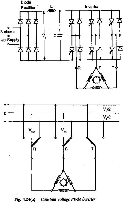
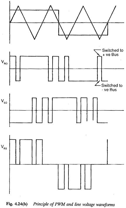
The problems can be reduced to a minimum if voltage control is obtained in the inverter itself. The inverter is supplied with constant dc voltage and the inverter is controlled so that the average amplitude of the output voltage is variable. By this, the operation of the inverter can be extended up to zero frequency, as the commutation is effective at all frequencies. By this control the output voltage is no longer a square wave but a pulsed wave, the average of which tends to be sinusoidal if sinusoidal modulation is used. The Working Principle of PWM Inverter and output voltage waveform are shown in Fig. 4.24. The stator current also tends to be sinusoidal. Harmonic effects are reduced to a minimum and torque pulsations are minimal. The dynamic behaviour of the drive at low speeds is improved. As there is no limitation on the lowest frequency the speed range of the drive is 1 : ∞.
The machine need not be specially designed to have large leakage reactance. Normal motors can be employed and the inverter output waveform causes the least harmonic effects. The filter size in the dc link can be smaller. The peak currents are also small and hence the converter design rating decreases. However the methods of modulation employed make the control circuit complex and costly. The frequent switching of the thyristors introduces switching losses and these PWM Inverter are built to an upper frequency of 150 Hz. A slip controlled drive is possible. Dynamic braking can be employed. The K.E. of rotating parts is dissipated in an external resistance. If a battery is used to supply the inverter, the regeneration is simple and straight forward. If the dc supply is obtained using a rectifier another phase controlled rectifier which is connected ‘antiparallel to the previous one is required on the line side. It is suitable for both single and multimotor operation. Uninterrupted operation can be made possible when a buffer battery is used.
During motoring a diode rectifier is sufficient on the line side and the line p.f. is better. Slip control can be had to keep the flux constant. Thus it has the merits of a slip controlled drive. Selected harmonic neutralisation principles can be used to eliminate lower order harmonics. Soft starting without any starting equipment is possible with acceleration and braking at constant torque.
The specific features of PWM Inverter Fed Induction Motor can be summarized as follows:
- The inverter has constant dc link voltage and employs PWM principle for both voltage control and harmonic elimination.
- The output voltage waveform is improved, with reduced harmonic content. The amplitude of torque pulsations is minimal even at low speeds.
- Parallel operation of many inverters on the same dc bus.
- Uninterrupted operation is possible when a buffer battery is used.
- The power factor of the system is good as a diode rectifier can be employed on the line scale.
- The control is complicated.
- Four quadrant operation is possible. During regeneration a battery or another converter with phase control may be used. Dynamic braking can also be employed.
- Single and multimotor operations are possible. Smooth changeover of voltage and frequency values at zero crossing for speed reversal with full torque capability at standstill.
- Due to switching losses, the highest operating frequency is 150 Hz. Speed range 1 : ∞.
- The PWM Inverter and load need not be matched. The converter operates as a source to which the motor can be plugged.
- The leakage reactance of the motor further smoothens the motor current, effectively decreasing the harmonic content and peak values of stator current.
- The size of the filter also decreases.
- The efficiency maybe affected by switching losses.
- Open loop operation is possible. The drive has a very good dynamic and transient response.
- Selected harmonic elimination techniques may be employed to eliminate lower order harmonics.
- The drive finds application in low to medium power. Commercial drives are available up to 450 kVA.
- Transistors may be used in place of thyristors.