Audio Frequency Transformer:
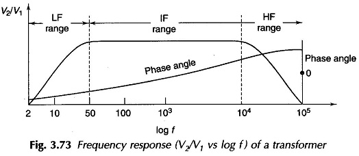
Audio Frequency Transformer is used at the output stage of Audio Frequency electronic amplifier for matching the load to the output impedance of the power amplifier stage. Here the load is fixed but the frequency is variable over a band (audio, 20 Hz to 20 kHz), the response being the ratio V2/V1. A flat frequency response over the frequency band of interest is most desirable. The corresponding phase angle (angle of V2 w.r.t. V1) is called phase response. A small angle is acceptable.
The Audio Frequency Transformer is used in electronic circuits (control, communication, measurement etc.) for stepping up the voltage or impedance matching. They are normally small in size and have iron cores. It is essential that distortion should be as low as possible.

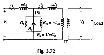
Figure 3.72 shows the exact circuit model of a Transformer with frequency variable over a wide range. Here the magnetizing shunt branch is drawn between primary and secondary impedances (resistance and leakage reactance). Also represented is the shunting effect of transformer windings stray capacitance Cs.
Audio Transformer Frequency Response:
In the intermediate frequency (IF) range the shunt branch acts like an open circuit and series impedance drop is also negligibly small such that V2/V1 remains fixed (flat response) as in Fig. 3.73.

In the LF (low frequency) region the magnetizing suceptance is low and draws a large current with a consequent large voltage drop in (r1 + j ωL1). As a result V2/V1 drops sharply to zero (at dc Bm = 0) (Fig. 3.73). In the HF (high frequency) region Bs = 1/ω Cs (stray capacitance susceptance) has a strong shunting effect and V2/V1 drops off as in Fig. 3.73, which shows the complete audio transformer frequency response on logarithmic frequency scale.
