Methods of Suppressing Unwanted Sidebands:
As stated earlier, the three practical methods of SSB generation all use the balanced modulator to suppress the carrier, but each uses a different method of removing the unwanted sideband. All three systems will remove either the upper or the lower sideband with equal ease, depending on the specific circuit arrangement. Each of the systems will now be studied in turn in the Methods of Suppressing Unwanted Sidebands.
The Filter System:
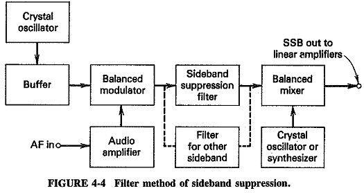
The filter system is the simplest system of the three after the balanced modulator the unwanted sideband is removed (actually heavily attenuated) by a filter. The filter may be LC, crystal, ceramic or mechanical, depending on the carrier frequency and other requirements. A block diagram of an SSB transmitter employing this system is shown in Figure 4-4.
The key circuits in this transmitter are the balanced modulator and the sideband-suppression filter. The special considerations involving Methods of Suppressing Unwanted Sidebands will now be examined.
Such a filter must have a flat bandpass and extremely high attenuation outside the bandpass. There is no limit on this; the higher the attenuation, the better. In radio communications systems, the frequency range used for voice is 300 to about 2800 Hz in most cases. If it is required to suppress the lower sideband and if the transmitting frequency is f, then the lowest frequency that this filter must pass without attenuation is f + 300 Hz, whereas the highest frequency that must be fully attenuated is f – 300 Hz. In other words, the filter’s response must change from zero attenuation to full attenuation over a range of only 600 Hz. If the transmitting frequency is much above 10 MHz, this is virtually impossible. The situation becomes even worse if lower modulating frequencies are employed, such as the 50-Hz minimum in AM broadcasting. In order to obtain a filter response curve with skirts as steep as those suggested above, the Q of the tuned circuits used must be very high. As the transmitting frequency is raised, so must the Q be raised, until a situation is reached where the necessary Q is so high that there is no practicable method of achieving it.
Looking at the situation from the other end, we find that there must be an upper frequency limit for any type of filter circuit used. It has been found, for instance, that multistage LC filters cannot be used for RF values much greater than about 100 kHz. Above this frequency the attenuation outside the bandpass is insufficient. LC filters may still be encountered in currently used HF equipment, but they have otherwise tended to be superseded by crystal, ceramic or mechanical filters, mainly because of the bulky size of components and great improvements in mechanical filters. Mechanical filters have been used at frequencies up to 500 kHz, and crystal or ceramic filters up to about 20 MHz.
Of the three major types of SSB filters, the mechanical filter seems to be the one with the best all-around properties, small size, good bandpass, very good attenuation characteristics and an adequate upper frequency limit are its chief advantages. Crystal or ceramic filters may be cheaper, but are preferable only at frequencies above 1 MHz.
All these filters (even the crystal) have the same disadvantage their maximum operating frequency is below the usual transmitting frequencies. This is a reason for the balanced mixer shown in Figure 4-4. (It is very much like a balanced modulator, except that the sum frequency is much farther from the crystal oscillator frequency than the USB was from the carrier, so that it can be selected with a tuned circuit.) In this mixer, the frequency of the crystal oscillator or synthesizer is added to the SSB signal from the filter, the frequency thus being raised to the value desired for transmission. Such an arrangement also allows the transmitter to be tunable. If the transmitting frequency is much higher than the operating frequency of the sideband filter, then two stages of mixing will be required. It becomes too difficult to filter out the unwanted frequencies in the output of the mixer.
It might be noted that the mixer is followed by linear amplifiers. The reason is that the amplitude of the SSB signal is variable and must not be fed to a class C amplifier, which would distort it. A class B RF amplifier (push-pull) is used instead because it is more efficient than a class A amplifier. The name linear amplifier is not confined to SSB systems. Linear amplifiers are used in any AM system in which low or no signal distortion is a requirement.
The Phase-Shift Method:
The phase-shift method avoids filters and some of their inherent disadvantages, and instead makes use of two balanced modulators and two phase-shifting networks, as shown in Figure 4-5. One of the modulators, M1, receives the carrier voltage (shifted by 90°) and the modulating voltage, whereas the other, M2, is fed the modulating voltage (shifted through 90°) and the carrier voltage. Sometimes the modulating voltage phase shift is arranged slightly differently. It is made +45° for one of the balanced modulators and —45° for the other, but the result is the same.
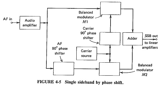
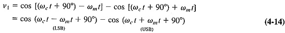
Both modulators produce an output consisting only of sidebands. It will be shown that both upper sidebands lead the input carrier voltage by 90°. One of the lower sidebands leads the reference voltage by 90°, and the other lags it by 90°. The two lower sidebands are thus out of phase, and when combined in the adder, they cancel each other. The upper sidebands are in phase at the adder and therefore add giving SSB in which the lower sideband has been canceled. The previous statements may be proved as follows.
If it is taken for granted that the two balanced modulators are also balanced with respect to each other, then amplitudes may be ignored as they do not affect the result. Note also that both balanced modulators are fed from the same sources. As before, taking sin ωc t as the carrier and sin ωm t as the modulation, we see that the balanced modulator M1 will receive sin ωm t and sin (ωct + 90°), whereas M2 takes sin (ωm t + 90°) and sin ωc t. Following the reasoning in the proof of the balanced modulator, we know that the output of M1 will contain sum and difference frequencies. Thus
Similarly, the output of M2 will contain

The output of the adder is
![]()
This output is obtained by adding Equations (4-14) and (4-15) and observing that the first term of the first equation is 180° out of phase with the first term of the second. We have proved that one of the sidebands in the adder is canceled. The other is reinforced. The system as shown yields the upper sideband. A similar analysis shows that SSB with the lower sideband present will be obtained if both signals are fed (phase-shifted) to the one balanced modulator.
The “Third” Method:
The third method of generating SSB was developed by Weaver as a means of retaining the advantages of the phase-shift method, such as its ability to generate SSB at any frequency and use low audio frequencies, without the associated disadvantage of an AF phase-shift network required to operate over a large range of audio frequencies. The third method is in direct competition with the filter method, but is very complex and not often used commercially.
From the block diagram of Figure 4-6, we see that the latter part of this circuit is identical to that of the phase-shift method, but the way in which appropriate voltages are fed to the last two balanced modulators at points C and F has been changed. Instead of trying to phase-shift the whole range of audio frequencies, this method combines them with an AF carrier f0, which is a fixed frequency in the middle of the audio band, 1650 Hz. A phase shift is then applied to this frequency only, and after the resulting voltages have been applied to the first pair of balanced modulators, the low-pass filters whose cutoff frequency is f0 ensure that the input to the last pair of balanced modulators results in the proper eventual Methods of Suppressing Unwanted Sidebands.
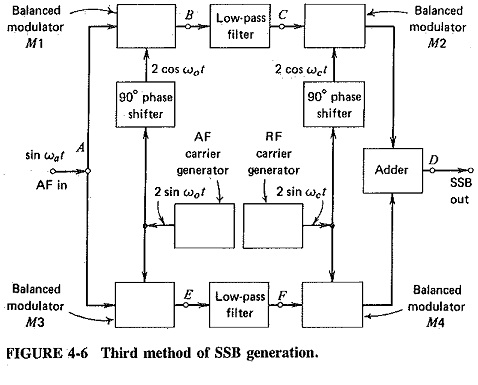
The proof of this method is unduly complex, and therefore not given here. It may be shown that all lower sideband signals will be canceled for the configuration of Figure 4-6, regardless of whether audio frequencies are above or below f0. If a lower sideband signal is required, the phase of the carrier voltage applied to M1 may be changed by 180°.
System Evaluation and Comparison:
The same SSB is generated regardless of which method of generation is used. An acceptable single-sideband suppressed-carrier signal is obtained, with either sideband removed. It has also been found from subjective listening tests that the quality is much the same from all three systems. To put each system into the proper perspective, it is necessary to examine the technical differences of the three methods of generation.
The filter system gives more than adequate Methods of Suppressing Unwanted Sidebands (50 dB possible), and the sideband filter also helps to attenuate the carrier, adding a safety feature which is absent from the two phasing systems. The bandwidth is sufficiently flat and wide, except possibly with crystal filters at the lowest frequencies, where it tends to be restricted and to give a “tinny” quality. The big disadvantage of this system had been its bulk, but this has been overcome with the advent of small mechanical filters of excellent quality and crystal filters of reduced size. The main disadvantage now is the inability of this system to generate 5513 at high radio frequencies, so that repeated mixing is required in conjunction with extremely stable crystal oscillators. Also, there are the limitations that low audio frequencies cannot be used, and that two rather expensive filters are required with each transmitter to make it capable of suppressing either sideband at will. This is an excellent means of generating SSB of communications quality. It is used in a vast majority of commercial systems, particularly with mechanical filters, except in multichannel equipment, where crystal or even LC filters are often used.
The phase-cancellation method was originally introduced to overcome the bulk of the filter system using LC filters. Since these have now been replaced by much smaller filters, this initial advantage no longer applies, but there are still two others. The case of switching from one sideband to the other and the ability to generate SSB at any frequency, rendering mixing unnecessary. In addition, low audio frequencies may be used for modulation. On the debit side, we have the critical AF phase-shift network. Whereas the RF phase shifter operates at one frequency only and is therefore a very simple RC circuit, the audio phase shifter is a much more complex device since it has to work over a large frequency range. If the phase shifter provides a phase change other than 90° at any audio frequency, that particular frequency will not be completely removed from the unwanted sideband.
In addition, the system has two balanced modulators, which must both give exactly the same output (this assumption was made in the proof ), or the cancellation will again be incomplete. Finally, it has been found in practice that layout is quite critical with this system. The result of all these considerations is that the phase-shift system is not used commercially, but it is employed widely by amateurs since filters tend to be rather expensive.
The third method requires neither a Methods of Suppressing Unwanted Sidebands filter nor a wideband audio phase-shift network. Correct output can be maintained simply without critical parts or adjustments. Low audio frequencies may be transmitted if desired, and since the majority of the circuitry is at AF, layout and component tolerances are not critical. Sidebands may also be switched quite easily, but an extra crystal may be required for this procedure. On the other hand, dc coupling may be needed to avoid the loss of signal components close to the audio carrier frequency. Whistle will exist at that frequency if the balance of the low-frequency balanced modulators deteriorates. This system is the most complex of the three. It has a disadvantage because the filter method works so well for present requirements. Although the third method has been used commercially, present indications are that it is unlikely to replace the filter method.