Power Factor Improvement Methods:
There are many drives which operate at a low power factor. Some of Power Factor Improvement Methods are:
- An induction motor direct on line.
- ac-dc diode rectifier and line commutated thyristor converter fed dc motor and variable frequency ac motor drives.
- ac regulator fed induction motor drives.
- Induction motor drive with slip power recovery.
Due to wide spread use of these drives, Power Factor Improvement Methods has become an important issue. A good power factor:
- decreases the copper loss in transformers, disiribution cables, transmissions line and other equipments, thus allowing considerable saving in energy consumptions.
- helps in stabilizing the system voltage.
- reduces the load on transmission and distribution equipment and transformer. Thus, it allows transmission of larger power and full utilisation of substation and generating unit
- avoids large penalty often imposed on low power factor consumers by the utilities.
Definition of Power Factor:
In linear loads, power factor (PF) is defined as:
![]()
where Φ is the phase angle between phase voltage and phase current of the load. Further for a three-phase load
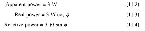
where V is the phase voltage and I the phase current of the load, respectively.
When a nonlinear load is fed from a sinusoidal supply, current will consist of fundamental and harmonics. The power factor for a nonlinear load is defined as:
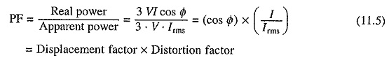
where V is the fundamental component of source voltage and also rms value of source voltage as source is sinusoidal; I the fundamental component of load current; Irms the rms value of the load current and Φ the phase angle between V and I.
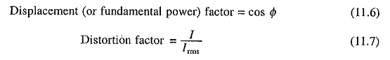
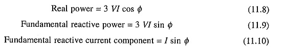
In a nonlinear load good power factor is achieved when both displacement and distortion factors approach unity. Further
Among the drives listed can be considered to be a linear load, and (b) to (d) are non-linear loads. Following methods are employed for the improvement of power factor of linear loads and displacement factor (or fundamental power factor) of nonlinear loads:
Overexcited Synchronous Motors:
When connected direct on line, a synchronous motor runs at a constant speed. It draws leading reactive power when overexcited. The leading reactive power can be controlled by the control of machine’s field excitation. In a plant involving several drives, synchronous motors can be employed in few drives where speed control is not required. By controlling their field excitation by a closed-loop control, their leading reactive power can be made to track the lagging reactive power of the rest of the plant loads, including drives. Thus the overall plant power factor can be maintained close to unity.
When the overexcited synchronous motor is used only for Power Factor Improvement Methods (i.e. does not drive any load) it is known as synchronous condensator.
Capacitors:
There are large number of applications where speed control is not required. Induction motors are widely used in these applications. Power factor of such drives can be corrected (improved) by permanently connecting a fixed capacitor across the motor terminals.
One important case is of agriculture pump drives. These drives operate nearly at constant average power but at low power factor. By installing a capacitor across the motor, power factor can be maintained high. Noting that agriculture pumps form a major load on the utility, around 30% in several states in India, the power factor correction can bring about many benefits listed above, including large saving in energy.
The choice of capacitor value should be done carefully. In no case over-compensation should be permitted because it causes overexcitation of the motor resulting in high transient voltages, currents and torques which can cause possible damage to the motors and driven machinery and can increase safety hazards to operators.
A drive generally operates at variable loads. If a capacitor value is selected based on full load reactive power, the drive is likely to work with overexcitation at lower loads. In view of this, it is more appropriate to size the capacitor to compensate from 90 to 100% no load lagging reactive power of the motor. This will ensure good power factor at all loads without overexcitation.
Location of the capacitor is also very important. Best location for connecting capacitor is directly across the motor terminals; because then no extra switches or protective devices are required, line losses are reduced from the point of connection to the source, and the capacitor is supplied only when motor is operating. If motor is provided with an overload relay protection, relay setting will have to be reduced, because for a given overload, current drawn by the capacitor motor combination will be less than the current drawn by motor alone. In a plant with multiple motors, power factor correction capacitor can be connected at the common input point, because a single capacitor will be very cheap compared to several capacitors of small sizes. When all motors are not likely to work all the time, more than one capacitor can be used and arrangement can be made with the help of relays and contactors to switch them in and out in order to match the leading reactive power drawn by capacitors with the lagging reactive power of the plant.
The power factor correction by capacitor should not be used for following cases:
- When motor is coupled to an active load: Active load may drive the motor as a generator. A part of regenerated energy may be stored in the capacitor causing its voltage to rise beyond the safe value.
- In pole changing motors: When connections of the motor running at higher speed are changed to reduce speed, motor regenerates until new steady state speed is reached, posing the problem mentioned in (i).
- When motor is started by open circuit transition.
- When motor is frequently subjected to transient operations such as starting, inching and
- Applications involving reversal by plugging.
- When motor is fed from a semiconductor converter: Transient current peaks produced by the capacitor can damage the converter.
- When motor is fed from a variable frequency source.
Capacitors can also be used for the compensation of loads with variable reactive power, as already mentioned earlier in this section. It will be necessary to use few capacitors which can be switched in and out to match the leading reactive current of capacitor bank with the lagging reactive power of the load. But such an arrangement has several disadvantages. Switching in of capacitors may produce transients of objectionable magnitude. Further, contactor and relay contacts will need frequent replacement. In view of this, for variable reactive power loads static var compensators employing thyristors are preferred.
Static var compensators:
A synchronous condenser can be used for the compensation of the load with variable reactive power. However, static var compensators are preferred because of several advantages like lower cost, lower losses, fast response, lower maintenance and quiet operation.
In case of nonlinear loads, power factor is the product of displacement factor (or fundamental power factor) and distortion factor. Therefore, Power Factor Improvement Methods of both—displacement and distortion factors. Above discussion is confined to the improvement of only displacement factor. The distortion factor can be improved by filtering out harmonics in the input current and voltage of nonlinear loads.
Let us consider two examples for further clarification of these points:
- A diode bridge rectifier always operates at unity displacement factor, but its power factor is low due to low distortion factor. Therefore, filters are connected at its input terminals to filter out harmonics.
- A line commutated thyristor converter operates at a low displacement factor and a low distortion factor. When its power rating is large, as in traction locomotive, a static var compensator is employed to improve displacement factor and filters are employed to improve distortion factor.
Harmonics produced by nonlinear loads (b) to (d), apart from reducing power factor, create following problems:
- They interfere with other loads on the same line.
- Produce electromagnetic interference.
- Saturate and overheat transformers and motors on the same line. Increase noise.
- Overheating of capacitors leading to their failure.
- Malfunction of electronic equipment and protective devices.
- Increase in line losses.
For nonlinear loads of large capacities filters are always employed to get rid of these problems also. In a plant if the nonlinear loads form a significant proportion of its capacity (more than 20%), though none of the nonlinear load may have large capacity, then also filters may be used at suitable locations.