Methods to Leading Power Factor:
We have seen that a phase controlled converter requires reactive power for control and commutation. The harmonics do not contribute to the active power loading but they contribute to the reactive loading of the line. Because of these the line power factor is poor. A semi converter has been found to improve the reactive power requirement which Leading Power Factor. But it has a disadvantage that it cannot be used if regenerative braking is required. Optional freewheeling is a solution for this, but the control system becomes complex.
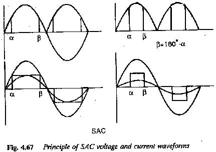
Several forced commutation methods are available to improve the performance of dc motors operating on phase controlled converters. These can be broadly divided into single firing and multiple firing schemes. In single firing schemes a thyristor is triggered once every half cycle and it is turned off using forced commutation. This means that the angle of quenching of the thyristor is also varied. These single firing schemes are extinction angle control (EAC) and symmetrical angle control (SAC) (Fig. 4.66). In normal phase angle control using natural commutation, the turn off of the thyristor takes place naturally. The drive performance has been discussed in detail. In EAC a thyristor is fired at its natural firing instant and its quenching angle β is varied. The commutation of the thyristor is achieved by one of the forced commutation methods. In the symmetrical angle control, if a is the firing angle, the angle of quenching β=180 – α. Thus both α and β are varied.
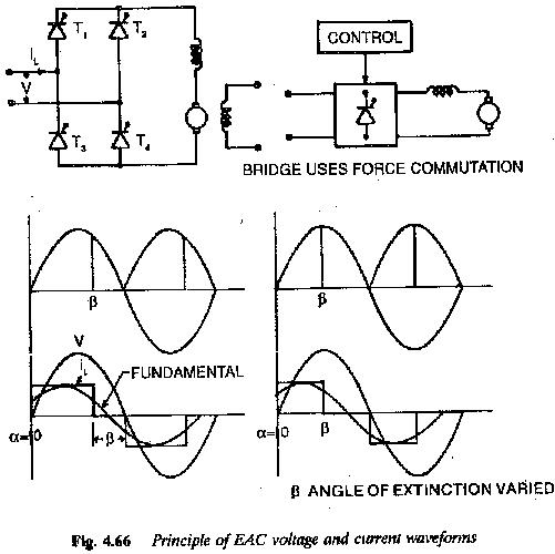
The waveforms of voltage and current are shown in Fig. 4.67 for all the cases. PAC waveforms are also included for comparison. The waveforms of PAC show deteriorating fundamental displacement factor as a is varied. In the EAC the angle of quenching is varied to vary the applied voltage to the motor. Fig. 4.66 shows that the fundamental of the input current pulse leads the applied voltage. Besides Leading Power Factor, EAC provides the effects of a leading power factor. In SAC both angle of firing as well as quenching are varied such that a symmetrical current pulse is obtained. The width of the current pulse changes with the control. The fundamental of this current pulse changes in amplitude but is fixed with respect to the voltage wave as shown in Fig. 4.67. The fundamental displacement factor is always unit and it is independent of a. This Leading Power Factor.
In all the single firing schemes there is a possibility of the load current becoming discontinuous. This happens particularly at light loads and when the armature inductance is low. Discontinuous conduction affects both the static and dynamic behaviour of the motor and the drive performance is poor. The peak armature currents cannot be controlled and hence commutating capability of the motor gets impaired. Harmonic losses are more and the motor heating limits the torque capability of the motor. The ripple content causes torque pulsations. It also makes the armature current discontinuous. The peak/average and rms/average current ratios can be reduced by a proper additional inductance in the armature circuit. This adds to the bulk of the system, makes the transient response sluggish and introduces additional losses.
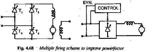
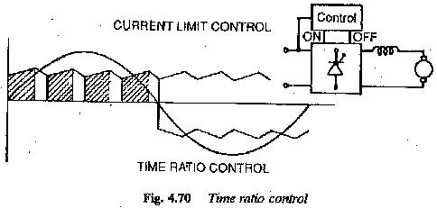
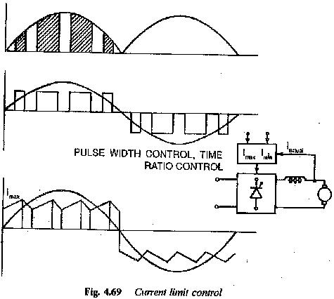
In the multiple firing schemes a thyristor is triggered ON and OFF several times in a half cycle. Obviously the schemes employ forced commutation, These are again current limit control (CLC) and the time ratio control (TRC) (Fig. 4.68). In the former the converter thyristors are turned ON and OFF such that the motor current varies between two limits. When the motor current reaches the upper limit the thyristor is turned off. The motor current freewheels and decays. When it decays to the lower limit the thyristor is again fired. The waveforms of voltage and current are shown in Fig. 4.69. The difference between the two limits determines the switching frequency and ripple content in the armature current. If the difference is small the ripple content is also small, but the switching frequency is large. This introduces switching losses. A compromise has to be made. The peak current can be controlled thereby improving the commutating capability of the motor. The discontinuous conduction can be eliminated. From the figure it is clear that the fundamental displacement factor is unity. As the harmonic factor is also improved there is a net Leading Power Factor. The inductance in the load circuit for smoothing purposes is rather small and this improves the dynamic response.
In the time ratio control the TON and TOFF of the thyristor are of given value. These are variable for variation in the output voltage. During TON the voltage is applied to the motor and the motor current increases. During TOFF the motor is switched off and the current decays. The waveforms are shown in Fig. 4.70. The switching frequency is predetermined. The ripple content is reduced by the large number of switchings per cycle. This increases switching losses. The peak current is not under control. There is possibility of discontinuous conduction. The ripple content may be more. The performance of the motor is slightly inferior compared to CLC, but it is improved in comparison with single firing schemes. In this scheme also, the fundamental displacement factor is unity. The improvement in the total power factor depends on harmonic content.