Buck and Boost Method of Speed Control in Traction:
The circuit diagram of buck and boost method of speed control in electric traction is shown in Fig. 13.15. The armatures of both the traction motors I and II and M-G set are connected in series. The whole series combination is connected across the supply. When the generator terminal voltage is equal to supply voltage in magnitude but of opposite polarity and the main contactor MC is closed, the voltage across the traction motors is zero and thus their speed is also zero. On reducing the generator voltage, voltage across the traction motors will start increasing and so their speed too.
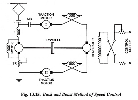
When the generator voltage becomes equal to zero, full line voltage will appear across both the motors i.e., one-half of the supply voltage across each motor. In case polarities of both supply source and generator are same and generator voltage is equal to supply voltage, voltage across each traction motor will be equal to supply voltage. Thus the voltage across traction motors can be adjusted (bucked or boosted up) by adjusting the excitation of the generator.
Advantages of Buck and Boost Method of Speed Control in Traction:
- Traction motors can be operated on any speed, while in case of resistance control only a few speeds are possible.
- There is no energy loss in the starting resistance of the traction motors. However, there is a loss of energy in the starting resistance of the M-G set.
- In case of temporary interruption in the supply, the kinetic energy of the flywheel can be utilized in generating energy from the M-G set and supplied to the traction motors.
Disadvantages:
- The main drawback of this method of speed control is requirement of M-G set. There is a loss of energy in M-G set.