Ward Leonard Method of Speed Control:
Known after the name of its inventor Ward Leonard Method of Speed Control (1891), it consists of a separately excited generator feeding the dc motor to be controlled. The generator is driven at a constant speed by an ac motor connected to 50 Hz ac mains. The driving motor may be an induction or a synchronous. When the source of power is not electrical, generator is driven by a non-electrical prime mover such as diesel engine or gas turbine. While the dc motor may be driven at low speeds, resulting in high torque and relatively large frame size, generator being of the same voltage, current and power ratings as the motor can run at a higher speed with a view to reduce its cost and size.
Motor terminal voltage is controlled by adjusting the field current of the generator. When field winding voltage is smoothly varied in either direction, the motor terminal voltage and therefore, speed can be steplessly varied from full positive to full negative.
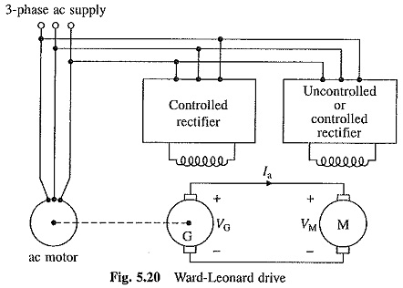
Block diagram of a Ward-Leonard scheme employing an ac motor for driving dc generator is shown in Fig. 5.20. One of the important features of this drive is the inherent ability for regenerative braking down to very low motor speeds. This combined with the variation of armature voltage in either direction allows efficient operation of drive in all the four quadrants of speed-torque plane. For regenerative braking, the output voltage of generator G is reduced below the induced voltage of motor M by decreasing the generator field current. This reverses the current flowing through the armatures of machines G and M. Now machine M works as a generator and G as a motor. Mechanical energy provided to machine M, either from the kinetic energy of rotating parts or due to an active load acting on its shaft, is converted into electrical energy. Electrical energy supplied by Machine M is converted into mechanical energy by machine G. The ac motor, which now works as a generator, converts the mechanical energy to electrical energy and feeds it to the ac source.
Control of generator field is obtained by rheostats when low ratings are involved and closed-loop control is not desired. Power requirement of the rheostats is of the order 1 to 2% of the total input to the motor. For higher power applications or for closed-loop control, the field is supplied by a power amplifier which may consists of a controlled rectifier, chopper or transistor amplifier. Old installations may use a magnetic amplifier or amplidyne. For reversible drives, a power amplifier capable of supplying controlled field current in either direction is required. It may, therefore, consists of a single-phase or three-phase dual converter, four quadrant chopper or four quadrant transistor amplifier. When the drive operates only in one direction, a power amplifier capable of supplying controlled field current only in one direction is used in order to reduce cost. The power amplifier may then consists of a half-controlled rectifier, step-down chopper or one quadrant transistor amplifier. In this case the field current can only be reduced, to zero, but cannot be reversed.
When the field is controlled by a power amplifier capable of supplying current only in one direction, the minimum speed obtainable is of the order 0.1 of base speed. This limit on the minimum value of speed is imposed because of the residual magnetism of generator field. Due to residual magnetism, even when field current is zero, enough voltage is generated to make the motor crawl particularly when the load is light.
To prevent crawling and to reduce the motor speed to zero, following three methods are employed:
(a) Armature circuit is opened.
(b) A differential field winding on the generator is connected across the armature terminals. Such a field will oppose the residual flux, and although it will not reduce the residual voltage to zero, it will prevent build-up of a large circulating current.
(c) The field winding of generator is connected across armature terminals such that the current through it produces mmf which opposes the residual mmf. This type of connection is commonly known as suicide connection.
The nature of speed-torque curves is similar to that shows earlier. Drop in motor speed due to change in load torque is caused by the drop of voltage across the armature resistances of the two machines. When motor speed, and therefore, generator output voltage is high, armature circuit resistance drop is only a small percentage of generator output voltage and, therefore, percentage speed regulation of the motor is good. At low speed, the armature resistance drop forms a large percentage of generator output voltage. This makes the percentage speed regulation not only large, the motor may stall with even slight increase in load torque.
When Ward Leonard Method of Speed Control in wide range is required, control of generator output voltage is combined with motor field control. Speeds below and above base speed are obtained by armature voltage control and motor field control, respectively. The maximum speed obtainable by motor field control is limited to twice base speed for normally designed and six times for specially designed motors. Combination of field control with armature voltage control permits the ratio of maximum to minimum available speeds to be 20 to 40. With closed loop control, the range can be extended further and can be realized up to 200. When field control is required, the motor field is fed from a half controlled rectifier, step down chopper or a single quadrant transistor amplifier. When not required motor field is fed from an uncontrolled rectifier. For low power application a resistance may be connected in series with the field.
As mentioned earlier, ac motor can be an induction or a synchronous motor. Though cheaper than synchronous, induction motor always operates at a lagging power factor. The synchronous motor can be operated at a leading power factor by overexciting its field. Leading reactive power produced by the motor compensates for the lagging reactive power taken by other loads in the plant, thus improving power factor of the plant. Over excitation of the field also enhances maximum torque capability of the motor. By employing closed-loop control of its reactive power, synchronous motor can be made to generate leading reactive power equal to lagging reactive power of the plant caused by other loads, making the plant power factor unity.
The Ward-Leonard drive is used in rolling mills, mine winders, paper mills, elevators, machine tools etc.
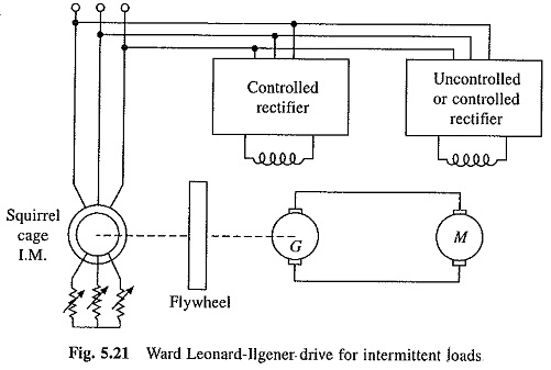
When the load is heavy and intermittent, a slip-ring induction motor is employed and a flywheel is mounted on its shaft. This is called the Ward-Leonard-Ilgener scheme (Fig. 5.21).
Rotor resistance control is used to restrict the motor current within permissible limits and to give it a drooping speed-torque characteristic. When heavy load demand comes, the flywheel decelerates and gives up some of its stored energy, thus reducing load demand from the supply. During light load periods, power is taken from supply to accelerate the flywheel, which replenishes the energy lost. This scheme provides two beneficial effects. First, it prevents heavy fluctuations in the supply current and secondly it permits the use of a relatively smaller size induction motor. This scheme finds application in the control of blooming mill drives and colliery winder in steel and mining industries, respectively. Because of large capacity of these drives (few megawatts), the fluctuations in supply current can lead to severe fluctuations of the supply voltage, which adversely affect other loads on the supply. Fluctuations can also have adverse effect on stability of the source.
It should be noted that when the ac motor is synchronous, supply current fluctuations cannot be reduced by mounting a flywheel on its shaft, because it operates only at a fixed speed. Therefore, a slip-ring induction motor is preferred over the synchronous when the load is intermittent and particularly when the drive capacity is large.
As explained above, the Ward Leonard Method of Speed Control has a number of advantages. It has inherent regenerative braking capability which allows efficient four quadrant operation. It can be employed for power factor improvement by using a synchronous motor. Because of the inertia of rotating machines, ac supply is dynamically decoupled from the load. For example, in paper mill drives, a short duration fluctuation of the supply voltage will not have any affect. Further, when it is used to supply important loads such as operation theatres, computers etc., where the continuity of supply is maintained at all costs, the inertia makes enough time available for uninterruptible power supply to take over in the event of failure of the mains supply. In intermittent load applications the Ward-Leonard-Ilgner driver prevents load torque fluctuations to cause source current and voltage fluctuations.
Main drawbacks of the Ward Leonard Method of Speed Control are its high initial cost and low efficiency because of the use of two additional machines of same ratings as that of the main motor, requires more frequent maintenance and produces more noise. Furthermore, it has large weight and size, and needs large floor area and foundation. Because of these drawbacks, the new installations mainly employ static Ward-Leonard drive, explained in Sec. 5.9. Exception is made in the case of high power intermittent load applications, such as blooming mill drives and mine winders, particularly when the supply system is weak. It can also be made for important loads where continuity of supply must be maintained at all costs.
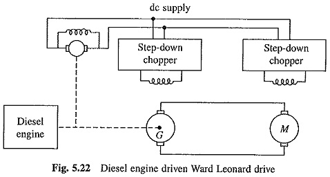
Another form of Ward Leonard Method of Speed Control employs a non-electrical prime mover to drive dc generator, e.g. diesel electric locomotive and ship-propulsion, where the generator is driven by a diesel engine or a gas turbine. The generator-motor combination works as a torque converter, like a step less gear, to impart to the motor speed-torque curves required by the load. While the motor runs at variable speed, the prime mover, and therefore, the generator runs at a fixed higher speed which may reduce their cost and size and optimize efficiency. Regenerative braking is not possible because the prime mover cannot allow the flow of energy in the reverse direction. However, dynamic braking can be used. The block diagram of such a drive for diesel electric locomotive is shown in Fig. 5.22. Here dc series motor is employed.
Commutator imposes a restriction on the maximum speed of a dc generator. This may not allow the prime mover to be driven at an optimum speed. Further, commutator also imposes restriction on the maximum power rating of a dc generator. In some large power applications, a number of motors are fed from a common generator. The generator should have a size larger than what can be accomplished by a dc generator. Furthermore, a dc generator also requires frequent maintenance because of commutator. In view of these limitations, a synchronous generator and an uncontrolled rectifier bridge are employed instead of a dc generator. Motor voltage is controlled by varying the field of the synchronous generator.