Ward Leonard Drive Transfer Function:
In the classical Ward Leonard Drive Transfer Function, the dc drive motor having constant excitation is supplied from a variable voltage generator, as shown in Fig. 6.9. The generator is driven at constant speed. The field current of the dc generator is varied by varying the field voltage to have variable voltage at the terminals, which is ultimately fed to the motor. A transfer function relating the speed of the motor and generator field voltage is required.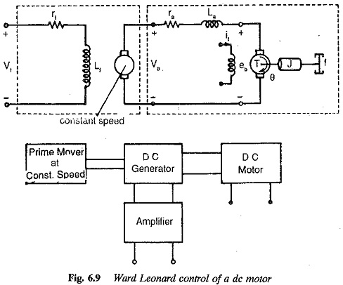
The system equations are![]()
The voltage induced in the armature of the generator is given by![]()
where Ka is a constant which includes the constancy of generator speed and the proportionality constant between field current and air gap flux. As usual the effects of saturation are neglected. Eliminating ifg from Eq. 6.30 we have
![]()
The transfer function between the armature voltage and field voltage of the generator is given by
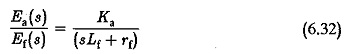
The transfer function of the armature controlled motor is
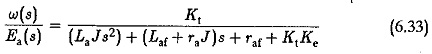
Combining Eqs 6.32 and 6.33, we have
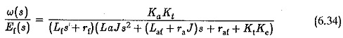
Neglecting the effects of La the transfer function simplifies in the second order to
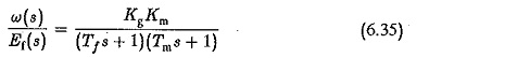
where
Kg = (Ka/rf) generator gain constant
Tf = Lf/rf generator field time constant
Km=Kt/(raf+KtKe) motor gain constant
Tm = raJ/(raf+KtKe) motor time constant
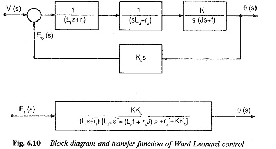
The block diagrams of a generator and a motor are shown in Fig. 6.10.
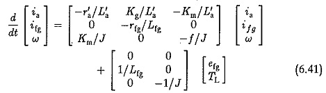
Alternately: The equations of the system may be derived in the state variable form taking if,ia and ω as the state variables. A signal flow graph may be drawn to represent these equations. Using Mason’s gain formula the transfer function may be derived.
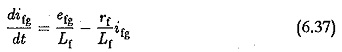
Using the schematic of Fig. 6.9 representing a Ward Leonard speed control system we have for the generator field circuit
![]()
which can be rearranged as
For the loop of armatures the circuit equation is given by
![]()
ea is the voltage induced in the armature of the generator and is given by Kgifg.
r′a and L′a include resistance and inductance of both generator and motor armatures respectively.
em is the back emf of the motor given by Kmω. Substituting in Eq. (6.37) and rearranging the terms we have
![]()
The torque balance equation gives the dynamics of the motor. It is
![]()
Rearranging the terms we have
![]()
Equations 6.40 are the state equations of the system and given in matrix rotation as