Reversible Drive using Field Reversal:
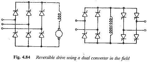
A Reversible Drive using Field Reversal can be realised as shown in Figs. 4.83 and 4.84. In Fig. 4.83, the armature is fed from a two quadrant converter with change over mechanical contactors in the field, which is also fed from a two quadrant converter.
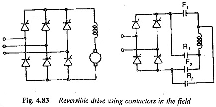
In the process of reversal of speed, the field current is reversed very fast using field forcing. Speed reversal using the above scheme is achieved in the following stages. F1 and F2 are for the forward direction and R1 and R2 are for reverse direction.
Stage 1: The motor is under a steady state, running at the rated speed in the forward direction. The converter in the field circuit is fired at a firing angle such that about 30% of the maximum voltage is the rated voltage of the Reversible Drive using Field Reversal and it is applied during running operation. For example αf = 70° and Vf = Vfm cos 70 = 0.34 Vfm,where Vfm is the voltage of the converter at zero firing angle.
Stage 2: This stage starts with a command of speed reversal. The converter feeding the armature is controlled (firing angle retarded) such that the armature current is zero (applied voltage E). The firing angle of the converter feeding the field circuit is retarded fully, taking the inverter limit into consideration. At this instant the converter voltage reverses and its magnitude would be 95% Vfm.
e.g., α is retarded to 170 and![]()
This voltage is three times the rated voltage in the reverse direction. The field current decreases very fast. The magnetic energy stored in the field is also fed back to the mains. During this time the motor back emf E also decreases.
When the field current reaches zero value, the contactors F1 and F2 are open and R1 and R2 closed. The field current flows in the opposite direction and is built up by increased voltage (α = 10)(.95 Vfm). As the field current builds up in the negative direction the motor retards regeneratively under constant armature current. The firing angle of the converter is changed such that normal voltage is applied to the field.
The motor speed reaches zero and it accelerates to the rated speed under constant armature current. At this point a load is applied to the motor.
When a dual converter is used in the field circuit for Reversible Drive using Field Reversal, it is preferable to operate it in the circulating current-free mode because the field current must go to zero. When a dual converter is used, the stages of speed reversal are almost the same as above. Converter I allows the current for forward rotation and converter II for reverse rotation. The only difference is, when once the field current has become zero the pulses to converter I are blocked and pulses to converter II are given. This requires a delay time similar to the one required by the contactors. Later, building up of current in the field and regenerative braking of the motor are similar.
These schemes have complex control circuitry. Even with field forcing, the response (time) of these schemes is slower than that of the schemes employing armature current reversal. The total speed reversal depends on the mechanical time constant of the drive.