Chopper Type DC Amplifier:
A simple ac amplifier Transformer may be used to amplify a dc input through the use of additional circuit component known as chopper. In this circuit, the dc signal is first converted into an ac signal, amplified by a standard amplifier, and finally converted back to a dc signal. The chopper can be electronic or mechanical. Figure 14.27 shows a chopper type dc amplifier.
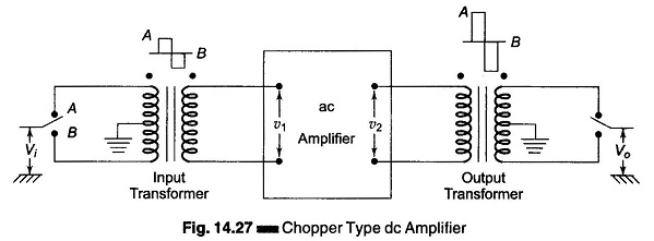
Vi is the input dc voltage, this voltage is alternately connected to terminals A and B. When the switch is in position A, the direction of current flow of the current is in one direction. When the switch is connected to position B, the current flows in the opposite direction.
This means that an ac voltage will be induced in the secondary winding of the input transformer.
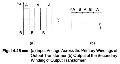
For an ideal transformer, this voltage is of perfect square wave shape. The peak value of the induced voltage is proportional to the dc input. The ac signal is amplified by a standard ac amplifier. An amplified square wave appears at the primary winding of the output transformer. The ac signal is converted back to dc. The secondary winding of the output transformer is centrally tapped, with an output switch ganged (mechanically coupled) to the input switch. The input voltage across the primary winding of the output transformer is shown in Fig. 14.28 (a) and the output of the secondary winding is shown in Fig. 14.28(b).
The amplifier of Fig. 14.27 is referred to as a chopper type dc amplifier, since the dc input voltage is literally chopped to produce ac signal. The chopping action may be accomplished by either mechanical or electronic means. A vibrating reed is used when mechanical methods are employed.