Variable Frequency Control of Induction Motor Drive:
Variable Frequency Control of Induction Motor Drive – Synchronous speed, therefore, the motor speed can be controlled by varying supply frequency. Voltage induced in stator is proportional to the product of supply frequency and air-gap flux. If stator drop is neglected, terminal voltage can be considered proportional to the product of frequency and flux.
Any reduction in the supply frequency, without a change in the terminal voltage, causes an increase in the air-gap flux. Induction motors are designed to operate at the knee point of the magnetization characteristic to make full use of the magnetic material. Therefore, the increase in flux will saturate the motor. This will increase the magnetizing current, distort the line current and voltage, increase the core loss and the stator copper loss, and produce a high-pitch acoustic noise. While an increase in flux beyond the’rated value is undesirable from the consideration of saturation effects, a decrease in flux is also avoided to retain the torque capability of the motor. Therefore, the Variable Frequency Control of Induction Motor Drive below the rated frequency is generally carried out at rated air-gap flux by varying terminal voltage with frequency so as to maintain (V/f) ratio constant at the rated value. From Eq. (6.13)
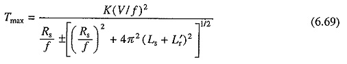
where K is a constant, and Ls and L′r are, respectively, the stator and stator referred rotor inductances. Positive sign is for motoring operation and negative sign is for braking operation.
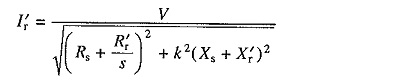
When frequency is not low, (Rs/f) ≪ 2π(Ls + L′r) and therefore, from (6.69)
![]()
Equation (6.70) suggests that with a constant (V/f) ratio, motor develops a constant maximum torque, except at low speeds (or frequencies). Motor therefore operates in constant torque mode. According to Eq. (6.69), for low frequencies (or low speeds) due to stator resistance drop [i.e. when (Rs/f) is not negligible compared to 2π(Ls + L′r)] the maximum torque will have lower value in motoring operation (-Eve sign) and larger value in braking operation (-ve sign). This behavior is due to reduction in flux during motoring operation and increase in flux during braking operation. When it is required that the same maximum torque is retained at low speeds also in motoring operation, (V/f) ratio is increased at low frequencies. This causes further increase in maximum braking torque and considerable saturation of the machine in braking operation.
When either V saturates or reaches rated value at base speed, it cannot be increased with frequency. Therefore, above base speed, frequency is changed with V maintained constant. According to Eq. (6.70), with V maintained constant, maximum torque decreases with increase in frequency (or speed).
Variation in terminal voltage with frequency is therefore as shown in Fig. 6.33(a). V is kept constant above the base speed. Below the base speed (V/f) ratio is maintained constant, except at low frequencies where (V/f) ratio is increased to keep maximum torque constant. Corresponding speed torque curves are shown in Fig. 6.33(b) both for motoring and braking operations. The curves suggest that speed control and braking operation are available from nearly zero speed to above synchronous speed.
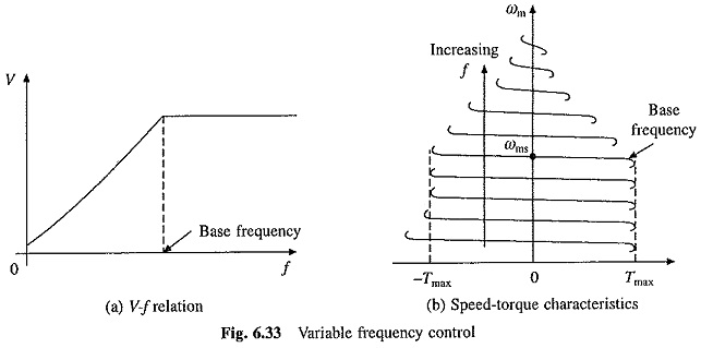
A given torque is obtained with a lower current when the operation at any frequency is restricted between the synchronous speed and the maximum torque point, both for motoring and braking operations. Therefore, the motor operation for each frequency is restricted between the synchronous speed and maximum torque point as shown by solid lines in Fig. 6.33(b).
The Variable Frequency Control of Induction Motor Drive provides good running and transient performance because of the following features:
- Speed control and braking operation are available from zero speed to above base speed.
- During transients (starting, braking and speed reversal) the operation can be carried out at the maximum torque with reduced current giving good dynamic response.
- Copper losses are low, and efficiency and power factor are high as the operation is restricted between synchronous speed and maximum torque point at all frequencies.
- Drop in speed from no load to full load is small.
The most important advantage of Variable Frequency Control of Induction Motor Drive is that it allows a variable speed drive with above-mentioned good running and transient performance to be obtained from a squirrel cage induction motor. The squirrel cage motor has a number of advantages over a dc motor. It is cheap, rugged, reliable and longer lasting. Because of the absence of commutator and brushes, it requires practically no maintenance, it can be operated in an explosive and contaminated environment, and can be designed for higher speeds, voltage and power ratings. It also has lower inertia, volume and weight. Though the cost of a squirrel cage motor is much lower compared to that of a dc motor of the same rating, the overall cost of variable frequency induction motor drives, in general are higher. But because of the advantages listed above, variable frequency induction motor drives are preferred over dc motor drives for most applications. In special applications requiring maintenance free operation, such as underground and underwater installations, and also in applications involving explosive and contaminated environments, such as in mines and chemical industry, variable frequency induction motor drives are a natural choice. They have several other applications such as traction, mill run out tables, steel mills, pumps, fans, blowers, compressors, spindle drives, conveyers, machine tools, and so on.
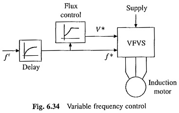
Block diagram of Variable Frequency Control of Induction Motor Drive scheme is shown in Fig. 6.34. The motor is fed from a variable frequency variable voltage source (VFVS). V* and f* are voltage and frequency commands for VFVS. Flux control block produces a voltage command V* for VFVS in order to maintain the relationship of Fig. 6.33(a) between V* and f*. Reference frequency f* is changed to control speed. A delay circuit is introduced between f* and fr, so that even when ft is changed by a large amount, f* will change only slowly so that motor speed can track changes in ft, thus restricting the motor operation for each frequency between synchronous speed and the maximum torque point. VFVS can be a voltage source inverter or a cycloconverter.
Slip Speed Control:
Let V and f denote the rated voltage and frequency of the machine. When the motor is operated below the base speed with constant (V/f) control, for a frequency, kf, the terminal voltage will be kV, where k is a factor such that, 0 ≤ k ≤ 1. Thus, as frequency is changed from 0 to f, k changes from 0 to 1 and voltage changes from 0 to V.
Substituting for voltage kV and for frequency kf and neglecting stator resistance drop, from Eqs (6.4) and (6.10)
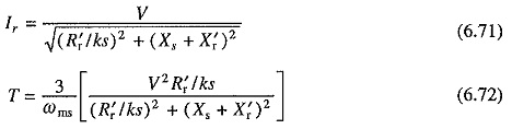
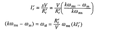
In Eqs. (6.71) and (6.72) if (ks) is maintained constant as k is varied, then rotor current I′r and torque T will remain constant. Since the slip is small I′r will be in phase with voltage. Since flux is constant Im will also be constant. Now
![]()
Thus if the motor operation is carried out at constant value of ks as the frequency is varied then the motor will operate at a constant current and torque. Let us examine the meaning of ks.
At frequency kf
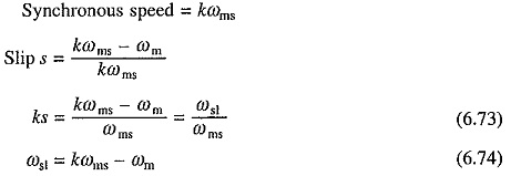
Note ωst is the slip speed, which is the difference in the rotating field speed kωms and rotor speed ωm. It is also the drop in motor speed from its no load speed, when the machine is loaded.
The above discussion shows. that for any value of T, the drop in the motor speed from its no load speed (kωms) is the same for all frequencies. Hence, machine speed torque characteristics for 0 < s < sm are approximately parallel curves.
Operation of the machine at a constant slip speed also implies the operation at a constant rotor frequency as shown below
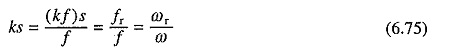
where fr and ωr are rotor frequency in Hz and rad/sec, respectively.
For s < sm, (R′r/sk) >> (Xs + X′r), hence from Eqs. (6.72) and (6.73)
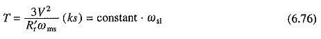
Eqn. (6.76) suggests that for s < sm, the speed torque curves are nearly straight lines. Since they are also parallel, the speed-torque curves are approximately parallel straight lines for s < sm.
According to above discussion, for a gives slip speed, motor current and torque have same values at all frequencies. Thus, motor current and torque can be controlled by controlling the slip speed. Further the motor current can be restricted within a safe limit by limiting the slip speed. This behavior is utilized in closed loop speed control for limiting the current within a permissible limit.
Let us next consider the operation above base speed. As stated earlier, machine operates at a constant voltage V. Now
As the frequency is higher than the rated k > 1. Since the operation is again constrained between the synchronous speed and the maximum torque, slip has a small value, hence
Thus for speeds above the base speed, at a given I′r and hence approximately at a given Is, the slip speed ωsl increases linearly with k (or frequency). This behavior is utilized in closed-loop speed control for limiting the current within permissible value above base speed.
Since the slip is small, I′r is in phase with V. If the machine copper loss is neglected, the developed power Pm is given by
![]()
Consequently, Pm is constant for a given I′r, and therefore for a given Is. The drive, therefore, operates in constant power mode.
Torque and Power Limitations, and Modes of Operation:
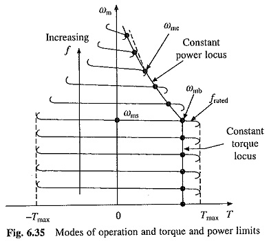
The torque and power variations for a given stator current and for frequencies below and above the rated frequency are shown by dots in Fig. 6.35. When the stator current has the maximum permissible value, these will represent the maximum torque and power capabilities of the motor in Variable Frequency Control of Induction Motor Drive.
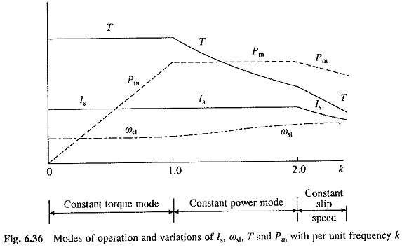
Variation of maximum torque and power capabilities with frequency are shown in Fig. 6.36. Variation of slip speed ωsl with frequency is also shown in this figure.
As seen in Figs. 6.35 and 6.36, the motor has a constant maximum torque from zero to base speed ωmb, hence the drive operates in constant torque mode. In this frequency range, V is changed with frequency as shown in Fig. 6.33(a) and the slip speed at the maximum permissible current remains constant. From base speed to speed ωmc, the maximum power has a constant value, hence the motor operates in constant power mode. At speed ωmc (Fig. 6.35), the breakdown torque is reached. Any attempt to operate the motor at the maximum permissible current beyond this speed will stall the motor. Hence, beyond the speed ωmc, the machine is operated at a constant slip speed and the maximum permissible current and maximum power are allowed to decrease (Fig. 6.36). Now the motor current reduces inversely with speed and torque decreases inversely as the speed squared. The operation in this region is required in drives requiring wide speed range but low torque at high speeds. For example in traction applications the drive operates in this region when running at full speed because the torque required in steady state at high speeds is very small compared to its value during acceleration.