Air Gap Power in Induction Motor | Torque and Power Output Equation:
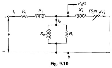
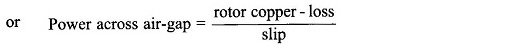
Air Gap Power in Induction Motor – The circuit model is shown in Fig. 9.10. The power crossing the terminals ab in this circuit is the electrical power input per phase minus the stator loss (stator copper-loss and iron-loss) and hence is the power that is transferred from the stator to the rotor via the air-gap magnetic field. This is known as the power across the air-gap and its 3-phase value is symbolized as PG. It is easily seen from the circuit model that

It also follows from Eq. (9.16) that
![]()
A part of this power is lost in the rotor copper which, if subtracted from PG, will give the mechanical power output (gross), i.e.

This means that the gross mechanical power output is three times (3-phase) the electrical power absorbed in resistance

Figure 9.10 can therefore be drawn as in Fig. 9.11 where R2‘/s is represented as
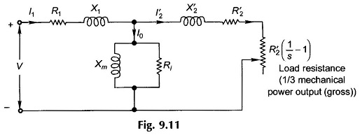

It is noticed from Eq. (9.18) that the mechanical power output is a fraction (1 – s) of the total power delivered to the rotor, while as per Eq. (9.17) a fraction s of it is dissipated as the rotor copper-loss. It is then evident that high-slip operation of the induction motor would be highly inefficient. Induction motors are, therefore, designed to operate at low slip (2-8%) at full-load.
Rotor speed is
![]()
The electromagnetic torque developed is then given by
![]()
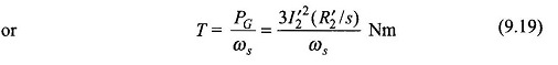
This is an interesting and significant result according to which torque is obtained from the power across the Air Gap Power in Induction Motor by dividing it with synchronous speed in rad/s as if this power was transferred at synchronous speed. It is because of this fact that PG, the power across the air-gap, is also known as torque in synchronous watts.
The net mechanical power output and torque are obtained by subtracting losses windage, friction and stray-load loss.
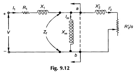
When dealing with power flows in the induction motor, it is common practice to employ the circuit model is shown in Fig. 9.12 wherein the net mechanical output and torque are obtained in the end by subtracting losses core loss, windage, friction loss and stray-load loss. The error introduced is negligible and the simplification is worthwhile.
Computational Procedure:
A convenient computational procedure for a given slip is to calculate in the circuit model of Fig. 9.12.

Then

It is always convenient to calculate on a per-phase basis and convert to 3-phase values in the end.