Air Blast Circuit Breaker:
Air Blast Circuit Breaker – It is not possible to produce a low resistance arc without a considerable gas pressure so that the only type available employs a high-pressure gas blast sweeping across the contact space. The gases which can be used are compressed air, nitrogen, carbon dioxide, hydrogen and freon. Now nitrogen is equivalent in circuit breaking properties to compressed air and therefore there is no advantage in using nitrogen. Carbon dioxide has the drawback of its being difficult to control owing to freezing at valves and other restricted passages. Tests have shown an increased breaking capacity by the use of hydrogen, but its cost and that of the ancillary apparatus are a serious objection. Freon has high dielectric strength and good extinguishing properties, but it is expensive and it is decomposed by the arc into acid forming elements. It follows from the above that compressed air is the accepted circuit-breaking medium for gas-blast circuit breakers.
All Air Blast Circuit Breaker follow the principle of separating their contacts in a flow of air established by the opening of a blast valve. The arc which is drawn is usually rapidly positioned centrally through a nozzle where it is kept to a fixed length and is subject to maximum scavenging by the air flow. Arrangements vary but can be grouped into three types as shown in Fig. (15.12): (a) axial blast, (b) radial blast and (c) cross blast. Axial or radial blast seems to be favored for the higher voltages although cross blast breakers particularly for voltages of about 15 KV and heavy current (up to 100 KA) have proved satisfactory and require less air than would an axial-blast breaker at these high currents.
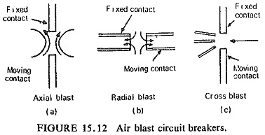
It is well recognized that the main structural advantage of the axial-blast circuit breaker over the cross blast is its easier adaptability to high voltage insulation particularly for outdoor applications. This is because the interrupting chambers can be fully enclosed in porcelain tubes. The axial blast type of circuit breaker thus is ideal for high and super voltage application and outdoors where dust and corrosive fumes are encountered. In the indoor high power medium voltage class of circuit breakers currents of 2000-4000A are common, requiring special multifinger contacts in order to keep the temperature low enough to prevent damaging oxidation. A multiple interruption by air blast can be arranged for very high voltages and exerting a joint radial and axial cooling by direct air convection. In order to secure high air velocities in Air Blast Circuit Breaker it is imperative to provide for relatively short wide passages for the air flow between pressure reservoir and arc. If the necessary volume of air is available near the arc, velocities exceeding that of sound may be attained at the critical instant of extinction.
Working Principle of Air Blast Circuit Breaker:
Gas blast interruption is dependent on turbulent cooling, and is therefore influenced by aerodynamic configuration, including nozzles, gas flow passages and mass flow. Compressed air is an excellent insulant, and is forced on the arc at the instant of contact separation. The compressed air the arc through the nozzle, which helps exhaust the hot gas and the arcing products to the atmosphere. In this way the interrupter of an Air Blast Circuit Breaker performs its operating cycle for its ideal characteristics. Extinction occurs at the first current zero when the flow of compressed air increases rapidly to establish the dielectric strength between the electrodes to withstand restriking voltage. The growth of dielectric strength is rapid and pressure of air is so high that the final gap caused by interposition of insulating layer of air between the contacts need only be small, thus reducing the size of the device. The energy supplied for arc extinction is obtained from high pressure air and is independent of the current to be interrupted.
Aerodynamic Effects During Arcing:
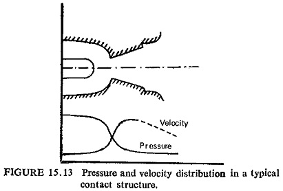
A knowledge of the air flow characteristics is important to circuit breaker design, since the removal of hot plasma and particulate matter determines both the interrupting ability and also the dielectric strength. Initiation of the lateral arc in the air turbulator causes a pressure disturbance in the flow of compressed air. The source of the disturbance (i.e. hot gas channel) being initially free, moves downstream at the same velocity as the compressed air. The are (i.e. hot gas channel) is thus transferred rapidly into such a position that it offers the maximum drag to the air flow, Lamely, into a central position along the axis of the nozzle. This rapid transfer is to be expected from a consideration of the velocity distribution in a typical air blast nozzle.
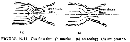
In this central position, the arc must either stand or fall. The ensuing aerodynamic condition at the nozzle may be regarded as a series of momentary disturbances of the flowing air due to the release of arc energy from a fixed source; these disturbances are such that throughout the arcing period, the stream of air tends to yield to the pressure caused by the expansion and dissociation of air in the inner stream zones as this air continuously enters the leading end of the arc zone. Conversely arc acts almost as an obstacle in nozzle, around which the bulk of air must flow. Figures (15.13) and (15. 14) illustrate pressure and velocity distribution and the gas flow through nozzles. It is seen that the presence of arcing causes considerable reduction in the quantity of air passing through the nozzle because of dissociation and expansion of air in the inner stream zones.
This effect is dependent on the length of arc at high pressure side of nozzle and on current flowing, i.e. the amount of preheating which air stream undergoes before reaching the throat of nozzle. At small currents the ionized arc column is repeatedly disrupted, and the electron discharge is interrupted; this is known as current suppression. At very large currents the air column gets heated up rapidly and the interruption becomes difficult and takes a longer time.
The aerodynamic arrangement of Air Blast Circuit Breaker is devised to make the ratio of air pressure at interrupting nozzles to the pressure in the receiver as high as possible. To this end, valve gear and pipe system should be made large and free from unnecessary bends, so that the major component of pressure drop occurs across the nozzles themselves.
Factors Influencing Performance of Air Blast Circuit Breakers:
There are a number of limiting parameters affecting the performance of the breaker; some of them lead to contradictory requirements that make the development of switch gear so difficult yet uniquely fascinating.
Some of the important factors are discussed below.
- Air Pressure.
- Circuit Severity.
- Distance between Contacts.
- Contact Material.
- Area of Cross Section of the Exit Hole.
- Resistance Switching.
- Mass Flow.
Construction of Air Blast Circuit Breaker:
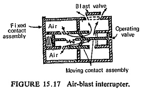
Figure 15.17 shows the essential elements of an air-blast interrupter. With the breaker closed, load current is carried by heavy copper main contacts. Following the instruction to trip, the air blast at about 2 MN/m2 (1MN/m2=145 psi=9.9 atmospheres) is turned on by the opening of a valve and the moving contacts set in rapid motion by the action of compressed air on a piston. As the contacts part, an arc is either drawn between special arcing contacts or transferred to them by the blast. The maximum separation of the contacts is in the region 10-20 mm and is commonly attained in 3 ms.
In actual Air Blast Circuit Breaker local air storage may be at earth potential and air supplied to the interrupters through insulating pipes or it may be mounted at the level of the interrupters at line potential and the air fed through insulating pipes. The blast valve may also be in one of many positions as given below:
- Receiver on the ground and blast valve at low level. Here the blast pipe must be filled before the interrupters are supplied with air.
- Receiver on the ground and blast valve at high level. This reduces the amount of air wasted but requires an insulated drive to the blast
- Live receiver and blast valve. Shorter opening times are possible as the air is stored near the interrupter units.