Air Break Circuit Breaker:
The arc interruption process of Air Break Circuit Breaker is based on the natural deionization of gases by a cooling action. The arc is resilient and can be stretched, and has resistance which can be increased both by length and confinement. Hence the increase of arc resistance is so high that the short-circuit current drops and the current and voltage are brought into phase. Reducing the phase difference between the system voltage and the short-circuit current assures that when the arc current is interrupted at its zero value, the recovery voltage has a very low value at this instant. Restriking voltage is thus reduced to a much smaller value and is not allowed to reach two-times the value of the system peak voltage, a phenomenon that occurs in most cases, when arc current is interrupted at low power factor by means of other conventional circuit breakers. The energy dissipated in the arc is however high and this limits the application of high-resistance interruption to low and medium power a.e. circuit breakers; it is also used for low and medium power d.c. circuit breakers.
Methods for Increasing Arc Resistance:
The following methods are employed for increasing arc resistance.
- Arc lengthening: Resistance is approximately proportional to length of the arc.
- Arc cooling: The voltage required to maintain ionization increases with a decrease of temperature so that cooling effectively increases the
- Arc splitting: An appreciable voltage is absorbed at the two contact surfaces so that if the arc can be split into a number of small arcs in series the voltage available for the actual arc column is reduced.
- Arc constraining: If the are can be constrained into a very narrow channel the voltage necessary to maintain it is increased.
The above-mentioned methods have been successfully carried out in the following types of Air Break Circuit Breaker.
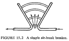
Plain Break Types:
This is the simplest type of Air Break Circuit Breaker where contacts are made in the shape of two horns. The arc initially strikes across the shortest distance between the horns, but it is then driven steadily upwards by the convection currents set up due to heating of air during arcing and the interaction of magnetic and electric fields. The arc extends from one tip to the other when the horns are fully separated resulting in arc lengthening and cooling. The relative slowness of the process and the possibility of the arc spreading to adjacent metal work limits the application to about 500 V and to low power circuits. Figure (15.2) shows such a breaker.
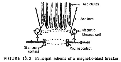
Magnetic Blow-Out Type:
In a number of Air Break Circuit Breaker used in circuits up to 11 KV the extinction of the arc is carried out by means of a magnetic blast. . To achieve this the arc is subjected to the action of magnetic field set up by coils connected in series with the circuit being interrupted. Such coils are called blow out coils, because they help in the arc being magnetically blown out. Figure (15.3) shows the principal scheme of a magnetic-blast circuit breaker. The arc is blown magnetically into arc chutes where the arc is lengthened, cooled and extinguished. The arc shields prevent spreading of the arc to adjacent metal work. As the breaking action becomes more effective with heavy currents, this principle has resulted in increasing the breaking capacities of these breakers to higher values.
Arc chute is an efficient device for quenching an arc in air, which performs three interrelated functions:
- It confines the arc within a restricted space.
- It provides magnetic control of the movement of the arc, so that extinction occurs within the device.
- It provides for the rapid cooling of the arc gases to ensure extinction by deionization.
Arc Splitter Type:
Here the blow-outs consist of steel inserts in the arcing chutes. These are so arranged that the magnetic field induced in them by the current in the arc moves it upwards still faster. The steel plates divide the arc into a number of short arcs in series. The distribution of voltage along the length of an arc. is not linear but is accompanied by a rather large anode and cathode drops. If the total sum of anode and cathode drops of all short arcs in series is more than the voltage of the circuit to be interrupted, conditions for quick extinction of the arc are automatically established.
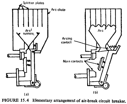
When the arc comes into contact with the relatively cool surfaces of the steel plates, it gets rapidly and effectively cooled. The movement of the arc may be natural or assisted by a magnetic blow-out, the latter is used for heavy duties up to 500 MVA at 16 KV. This type of breaker becomes more bulky, the arc chutes more complex and the initial cost higher as the voltage and MVA increase. Further Further the time of operation is not small enough to make this breaker suitable for modern power systems.
Application:
Air Break Circuit Breaker are, therefore, generally suitable for the control of power station auxiliaries and industrial plants. When they are chosen for such service, it is generally on the ground that they combine a high degree of safety with minimum maintenance. They also do not require any associated equipment such as compressors, etc. As they have no oil, they are recommended wherever fire or explosion hazards are to be feared.
General Design:
The breaker generally, consists of three single-pole units linked together by an insulated cross-bar, and operated by one or more mechanisms according to the current rating. The complete assembly, including the mechanism, is mounted on a panel of insulating material, with arc-resisting barriers on both sides of each pole.
Pole Unit: Each pole is made up on an independent insulating moulded piece on which are mounted main contacts, arcing contacts, arc chute, direct instantaneous releases and current transformers for operating thermal release.
Contacts: As a matter of fact there are many types of contacts used in different designs and it is beyond the scope of this book to describe all of them. However, one type will be discussed here.
(a) Main contacts: These carry the rated continuous current and consist of the moving contact assembly and the fixed contact assembly.
Moving contact assembly: These are solid copper spring-loaded rollers ringed with silver. The floating rollers turn around their axles by a few degrees each time the breaker is closed, assuring thereby a wiping action. The rotating action assures uniform wear and tear of the entire moving contact surface instead of a restricted part of the surface. The life of the moving roller contacts is therefore longer than standard leaf contacts.
Fixed contact assembly: These comprise two levelled copper, contact bars (line and load side) with silver pads at contact faces. The two fixed contacts are shunted by rollers. This arrangement assures an excellent durability of contacts and a minimum temperature rise. The design of the fixed contact is such that there is no other path than the main contacts for carrying the continuous current between line and load terminals.
(b) Arcing contacts: Arcing contacts have to undergo the effect of arcing and they open after and close before main contacts. Their shape is such that electrodynamic blow-on forces are used to compensate repulsion forces resulting in increased contact pressure to avoid any beat phenomenon, whatever be the time-delay of tripping.
Arc Chutes: All arc chutes are made of an insulating arc-resisting material, and surround each pole unit. The dimensions of the chute depend on the number of arcing contacts. The chute is shaped like a funnel with restricted area at its lower part. At the top, the arc chute houses a grid of steel plates the function of which is to increase the speed of rise of the arc into the chute by magnetic action. It also splits the arc and results in increasing the arcing voltage and deionizing the plasma by a strong cooling action.
Operating Mechanism: The mechanism for a.c. circuit breakers is usually designed for manual operation, but electrical operation such as electrical spring charged mechanism can be provided for remote control. The duties expected of a modern apparatus are: trip-free operation, independent opening, lockout feature preventing closing and, in the event of stored-energy operating-mechanism, independent closing.
Most types of operating mechanism have as their basis either the lever-and-toggle or the cam-and-roller system. The moving contact arm and its associated members are made as light as practicable in order to achieve the high breaking speed. Powerful springs are used to give rapid acceleration. Mechanisms are invariably of the trip-free type, and in some designs for manual closing there is included a device that causes immediate tripping if any reversal occurs in the direction of motion of the operating handle.
Automatic Releases:
The releases provided are:
- Overcurrent release
- Earth-fault release
- Undervoltage release
- Shunt-trip release
- Instantaneous short-circuit release.
The overcurrent release performs two important functions: (a) to trip the breaker on the occurrence of a short circuit, this is a short time delayed operation; (b) to trip the breaker in case of sustained overloads, whereas the instantaneous short-circuit release trips the circuit breaker when it is closed on a fault.