pH Measurement Methods:
pH is defined as the negative logarithm of the active hydrogen ion. It is a measure of the acidity or alkalinity of an aqueous solution. The pH scale runs from 0 – 14, with pH 7, the neutral point, being the pH of pure water at 25°C. The lower the pH value, the more acidic the solution. Increasing pH values above 7.0, indicate increasing alkalinity. Usually the pH is measured by immersing a special glass electrode and reference electrode into the solution. There are two types of pH measurement methods, the colorimetric method and the electrical method.
In this type of pH measurement method, colorimetric method is based on the assumption that if an indicator has the same colour in two solutions, then the pH of both solutions is the same. However, in practice this assumption does not hold good always, since the colour developed depends not only on the pH but also on other factors.
The electrical method is the most popular and is based upon a measurement of the electrode potential. The principle of this method is that when an electrode is immersed in the solution, a potential arises at the electrode solution boundary known as the electrode potential. This electrode potential, at a given temperature, depends upon the concentrations of ions of the electrolyte which exist in the solution. The electrode potential (in volts) of a metal immersed in a solution with ions of the same metal can be expressed by the following relation.
where
- Eo = potential of the electrode, when its active-ion concentration in the solution is equal to unity.
- t = temperature in degree centigrade
- n = valency of the ion
- a = active concentration of the ions of the metal in gram-equivalents per litre
In practice, only the potential difference can be measured and so the pH always has two elements; a measuring element, the potential of which depends on the concentration of the hydrogen ions, and a comparison element, the potential of which must remain constant. Two such elements connected electrically form a galvanic system, and by measuring the emf of this system we can drive the active concentration of the hydrogen ions in the solution under investigation.
The various electrodes used for pH measurements are as follows.
- Hydrogen electrode
- Calomel electrode
- Quinhydrone and antimony electrodes
- Glass electrodes
We now give some of the electrical methods used for measuring pH.
pH Measurement Using Hydrogen Electrode:
The hydrogen electrode comprises a platinum plate covered with platinum black kept in a hydrogen element, where gaseous hydrogen at atmospheric pressure acts directly on this plate.
It consists of a hollow tube which is opened at the bottom end and immersed in the solution whose pH value is to be measured. The platinum plate is inserted into this hollow tube and joined to the platinum wire which is welded to the glass tube. This platinum wire is joined to a copper lead, as shown in Fig. 10.24.
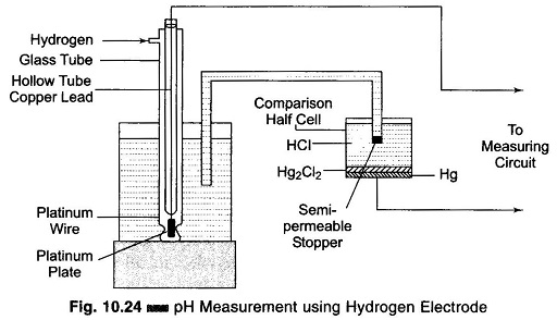
The hydrogen is fed to the outer tube from above and passes out through the lower apertures placed half way up the platinum plate. The hydrogen electrode is joined to the comparison half cell by an electrolytic solution. The cell is filled with an inert salt (for example, HC1) and closed by a semi-permeable stopper. This means of connecting the elements lowers the diffusion potential (up to 1 – 2 mV), which arises at the boundary of the two solutions and introduces an error in the result of the measurement.
The electric potential developed on a hydrogen electrode dipped in a solution is caused by the concentration of hydrogen ions in the solution, or the pH of the solution. By measuring this electric potential, the pH of the solution can be determined. There is no method by which the absolute value of the potential developed on the hydrogen electrode can be determined. It is always the potential difference between two objects or the potential difference between two points on the same object which is determined. Therefore it is possible only to determine the relative potential of the hydrogen electrode compared to the known potential of some reference electrode.
pH Measurement Using a Thermocompensator:
A thermocompensator is a temperature sensitive element (usually thermistor) installed in the solution with the electrodes. The glass electrode potential is influenced by changes in the temperature of the sample solution, and the thermocompensator corrects for this change. It should be noted that the thermocompensator corrects for toe voltage/temperature relationship of the glass electrode and does not correct for the actual changes in the pH of the solution with temperature variations. The use of a matched pair of thermistors can provide a linear temperature compensation response of 90% in less than one minute.
Differential Input pH Amplifier:
Differential input techniques use integrated circuit operational amplifiers in conjunction with a difference amplifier. This device is so small that it can be mounted on a single circuit board and sealed on top of the electrode station (provided the temperature to which it is subjected is less than 70°C; otherwise it is mounted in separate junction box suitably located at the site).
As the pH glass electrode is a high impedance device with output at extremely low current levels, a high impedance precision amplifier with high stability is required for the accurate and reliable measurement of this signal. The very high resistance of the glass electrode demands that the measuring techniques not require current when the reading is made. If any current is taken from the circuit, the portion of the emf used to force the current through the resistance subtracted from that originally available, and all values obtained are fictitiously low.
In a pH measurement system, any extraneous leakage current to the ground find a return path through the normally low resistance reference electrode. With a conventional single input amplifier, this extraneous voltage developed across the reference electrode adds to the measured pH potential, resulting in an error in the indicated pH. If the resistance of the reference electrode is relatively low, this error is usually insignificant. However, if this resistance increases due to coating or junction clogging, the extraneous voltage across it increases and can cause a significant error in the indicated pH.
In the differential input pH amplifier, the glass pH measuring electrode and the reference electrode are each inputted to separate high impedance constant gain integrated circuit operational amplifiers A1 and A2, with negligible current flowing through the electrodes. This arrangement is shown in Fig. 10.25.
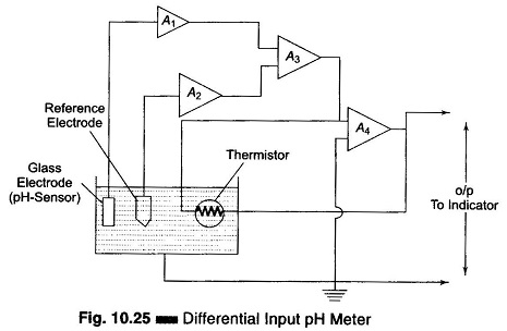
The glass electrode amplifier A1 measures the pH potential as well as any potential through the solution to ground. The reference electrode amplifier A2 measures the potential through the solution to ground. Amplifiers A1 and A2 are outputted to a difference amplifier A3 which cancels out the solution potential and produces a signal equal only to the pH potential.
This method has the following advantages.
- Virtually eliminates drift and noise
- Has no stringent installation and maintenance requirements
- Allows the pH indicator to be kept virtually any distance from the electrodes
- Eliminates the need for costly coaxial cables between the measuring point and the pH indicator
Instruments for the Measurement of emf of Electrodes for pH Measurement:
Indicating and automatic recording type instruments are used in industries for measuring the pH of different solutions. The pH is measured by measuring the difference of potential between the electrodes of the half cells. In order to eliminate distortions while measuring the emf of a sensor (e.g. the main sensing device of a pH Meter, which consists of the appropriate electrode), the magnitude of the input resistance of the measuring instruments must be at least two orders higher than the resistance of the electrodes. For example, if the resistance of glass electrodes is 1 – 2 x 10⁸ Ω, the resistance of the instrument must be about 1 – 2 x 10¹⁰ Ω. The dc voltage is transformed into ac voltage by frequency transformation circuits using either vibration converters or dynamic condensers.