Insulation Design of Circuit Breaker:
Insulation Design system of a circuit breaker requires solution of the following problems:
- Choice and calculation of the various clearances to be provided between the live parts and the dead parts in a circuit breaker.
- Calculation of voltages that will appear across each of the gaps in a multibreak system.
- Calculation of the minimum insulating levels to be provided for current carrying parts.
The choice of clearances to be provided around the live parts in a circuit breaker depends upon a study of the probable paths of electrical discharge. Care must be taken in defining these parts to take into account the possibility of the electric arc jumping out of the arc extinguishing chamber due to its faulty Insulation Design, the inadequate knowledge we have about the quantity, and the rate of gas production, etc.
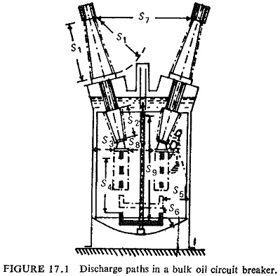
In Fig. (17.1) the various arc discharge paths that can be anticipated in a bulk oil circuit breaker are shown. Breakdown voltages of the paths have to be carefully decided taking into consideration the shape and condition of the various live parts. Further, certain special problems like the possibility of corona around some of the high voltage parts should also be considered.
Wherever multibreak systems are used the voltage distribution across each of the breaks will not be the same. For example, in an oil circuit breaker with two breaks, on a single phase to ground fault as much as 85% of the voltage may appear across one of the breaks.
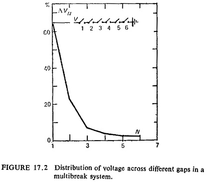
Figure (17.2) shows the percentage of the voltage appearing across each of the breaks in a six break system which clearly indicates the wide variations in voltages appearing across individual gaps. Steps should be taken in the Insulation Design to evaluate the values of shunting resistance to be used in multibreak systems in order to equalize to some extent the gap voltages.