Rogowski Coil Integrator Design:
If a Rogowski Coil Integrator Design is placed surrounding a current carrying conductor, the voltage signal induced in the coil is vi(t) = M dI(t)/dt where M is the mutual inductance between the conductor and the coil, and I(t) is the current flowing in the conductor. Usually, the coil is wound on a nonmagnetic former of toroidal shape and is coaxially placed surrounding the current carrying conductor.
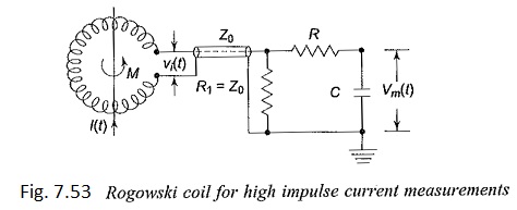
Where
- Vi(t) – Induced voltage in the coil = M d[I(t)]/dt
- Z0 – Coaxial cable of surge impedance Z0
- R-C – Integrating network
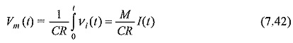
Usually an integrating circuit (see Fig. 7.53) is employed to get the output signal voltage proportional to the current to be measured. The output voltage is given by
Rogowski Coil Integrator Design with electronic or active integrator circuits have large bandwidths (about 100 MHz). At frequencies greater than 100 MHz the response is affected by the skin effect, the capacitance distributed per unit length along the Rogowski Coil Integrator Design, and due to the electromagnetic interferences. However, miniature probes having nanosecond response time are made using very few turns of copper strips for UHF measurements.
Magnetic Links:
Magnetic links are short high retentivity steel strips arranged on a circular wheel or drum. These strips have the property that the remanent magnetism for a current pulse of 0.5/5 μs is same as that caused by a d.c. current of the same value. Hence, these can be used for measurement of peak value of impulse currents. The strips will be kept at a known distance from the current carrying conductor and parallel to it. The remanent magnetism is then measured in the laboratory from which the peak value of the current can be estimated. These are useful for field measurements, mainly for estimating the lightning currents on the transmission lines and towers. By using a number of links, accurate measurement of the peak value, polarity, and the percentage oscillations in lightning currents can be made.
The rate of rise of impulse currents can be measured using the magnetic links by placing them within the magnetic field of inductors which carry the main current to be measured. The inductors are connected in series with different values of resistances giving different time constants. Hence the magnetic links record the peak currents whose values are different. Knowing the time constants of the resistance inductance combination, the mean rate of rise of current in the main circuit is estimated.
Different Techniques for Measurement of High Impulse Current:
1. Hall Generators:
Hall generators described earlier can be used for a.c. and impulse current measurements also. The bandwidth of such devices was found to be about 50 MHz with suitable compensating devices and feedback. The saturation effect in magnetic core can be minimized, and these devices are successfully used for post arc and plasma current measurements.
2. Faraday Generator or Ammeter:
When a linearly polarized light beam passes through a transparent crystal in the presence of a magnetic field, the plane or polarization of the light beam undergoes and the angle of rotation α is given by
![]()
where,
- V = a constant of the crystal which depends on the wavelength of the light,
- B = magnetic flux density, and
- l = length of the crystal.
To measure the waveform of a large current in an EHV system an arrangement shown in Fig. 7.54 may be employed. A beam of light from a stabilized light source is passed through a polarizer P1 to fall on a crystal F placed parallel to the magnetic field produced by the current I. The light beam undergoes rotation of its plane of polarization. After passing through the analyser, the beam is focused on a photomultiplier, the output of which is fed to a CRO. The output beam is filtered through a filter M, which allows only the monochromatic light. The relation between the oscillograph display and the current to be measured are complex but can be determined.
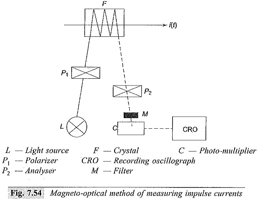
The advantages of this method are that
- there is no electric connection between the source and the device,
- no thermal problems even for large currents of several kiloamperes, and
- as the signal transmission is through an optical system, no insulation problems or difficulties arise for EHV systems. However, this device does not operate for d.c. currents.
3. Current transformers:
Measurement of high frequency currents such as fault currents in power systems, switching current transients and impulse currents during impulse testing of transformers can be measured using current transformers with an air core or a ferrite core. The transformer will have a torroidal core with central bar primary or wound primary with single turn.
The secondary side of the current with N1 primary and N2 secondary turns is given by (with perfect ampere turn balance)
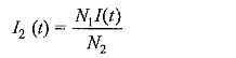
Usually the secondary winding is terminated by a resistance R2 and a CRO will be connected through a cable of surge impedance Z terminated by a resistance R equal to the surge impedance. The current I3 through the cable and terminating resistance R is
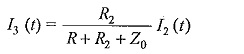
and the voltage across the resistance
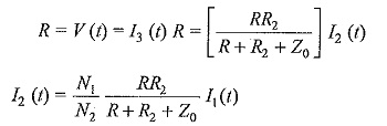
Usually R2 is also made equal to Z0 to avoid reflections in case of impulse currents.
The unit is usually made into an epoxy resin cast unit with primary and secondary terminals brought out on either side of the unit.
The advantages of the current transformer are electrical isolation and wide measuring range with tapped turns on secondary side from 10 A to 10 kA or more. The main limitations are limited bandwidth of less than 1 MHz, and distortion in the waveform.