Integrator using Op Amp:
An Integrator is a circuit that performs the mathematical operation of integration because it produces an output voltage that is proportional to the integral of the input. The Integrator using Op Amp is shown in Fig. 14.9.
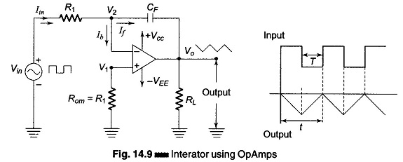
A common application is to use a constant input voltage to produce a ramp voltage. (A ramp voltage is a linearly increasing or decreasing voltage.) The typical input to the integrator is a rectangular pulse. Vin is the constant input voltage of time T applied to the inverting terminal. Because negligible current flows into the opamp, the input current is constant and equals Iin = Vin/R1. Approximately all the current goes to the capacitor CF. As C = Q/V or V = Q/C and since a constant current is flowing into the capacitor, the charge Q increases linearly. This means that the capacitor voltage increases linearly. Because of the phase reversal of the opamp, the output voltage is a negative ramp. At the negative pulse period of the input signal, the direction of the charging current is opposite, hence the output is an increasing ramp.
An integrator circuit is obtained by using a basic inverting amplifier configuration and by replacing the feedback resistor RF by a capacitor CF. The expression for the output voltage Vo can be obtained by using Kirchhoff’s current equation.
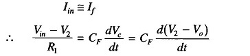
Iin = If + Ib, since Ib is negligible, Iin ≡ If. The current through the capacitor is given by
![]()
But

As
But
![]()
Therefore

The output voltage can be obtained by integrating both sides with respect to time, hence
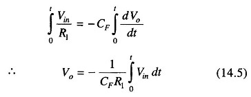
This equation says that the output voltage is directly proportional to the negative integral of the input voltage and inversely proportional to the time constant CF R1.
The input impedance of the Integrator using Op Amp circuit is equal to the resistance R1, the output impedance is low because of the negative feedback which is inherent in the circuit. CR is called the time constant of the integrator. For perfect integration, the time period T of the input signal must be longer than or equal to the time constant CF R1. In order to minimize the offset voltages, a resistor Rom called the “offset minimize resistor” is connected to the non-inverting terminal of the op-amp.
The integral of a sine function is a cosine function, hence, if a sine wave input is applied to an integrator, the output is a cosine wave. Also, if a square wave input is applied, the output is a triangular wave.
A practical Integrator using Op Amp is shown in Fig. 14.10.
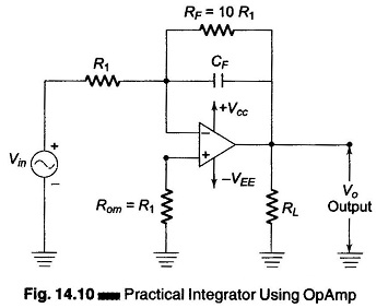
At low frequency and dc signals, the capacitor acts like an open circuit. Hence the closed loop voltage gain equals the open loop voltage gain. This produce too much output offset voltage. At zero frequency (DC) and without negative feedback, the circuit treats the input offsets as an valid input signal charges the capacitor. This drives the output into positive or negative saturation.
Hence a way to minimize the effect of these input offsets is to roll off the voltage gain at low frequencies by inserting a resistor RF in parallel with the capacitor, as shown in Fig. 14.10. The resistor used should be at least 10 times greater than the input resistance.
The integrator is most commonly used in analog computer, A/D conversion and signal wave shaping.