Vector Impedance Meter (Direct Reading):
If some knowledge of the reactive and resistive factors is needed, in addition to obtaining a direct reading of the magnitude of the impedance (Z), a test method for determining the Vector Impedance Meter may be employed.
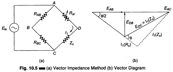
This method determines Z in polar form, that is, it gives the magnitude IZI and the phase angle (θ) of the impedance being tested, rather than the individual resistance and reactance in rectangular form, (R + j X). The test circuit is shown in Fig. 10.5. Two resistors of equal value R is used. The voltage drop across RAB and RBC, that is EAB and EBC will be equal (each value is equal to half the supply voltage, EAC). Since the same current I1 flows through the variable standard resistor Rst, the unknown impedance in series. The magnitude of Zx can be determined by the equal deflection method by obtaining equal voltage drops across Rst and Zx, i.e. EAD and EDC, and reading the calibrated standard resistor Rst, required to produce this condition.
The phase angle θ of the impedance Zx can be obtained from the reading of the voltage at points B and D, that is, EDB. The deflection of the meter will be found to vary with the Q of the unknown impedance Zx. The VTVM ac voltage reading will vary from 0 V, when the phase angle of 0° (Q = 0) to the maximum voltage, with an angle of 90° (Q = infinite). The angle between the voltages EAB and EAD is half the phase angle θ, since EAD is made equal to EDC.
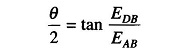
Since EAB is known to be half the known input voltage Ein, the voltmeter reading of EDB can be interpreted in terms of θ/2, and hence the phase angle θ of the unknown Zx can be determined.
While this method for obtaining both Z and θ is approximate because of the crowding caused by the non-linear relation, it is useful for obtaining a first approximation. A commercial Vector Impedance Meter is used for greater accuracy.
Commercial Vector Impedance Meter:
A commercial instrument that measures impedance directly in the polar form, giving the magnitude of Z in ohms, at a phase angle θ, requires only one balancing control for both values.
It measures any combination of R, L and C, and includes not only pure resistive, capacitive or inductive elements but also complex impedances. Since the determination of magnitude and angle requires only one balance control, the awkward condition of sliding balance, frequently encountered when measuring low Q reactors with conventional bridge circuits, which necessitates so much successive adjustments, is avoided.
Measurements of impedances ranging from 0.5 – 100,000 Ω can be made over the frequency range from 30 Hz to 40 kHz, when supplied by an external oscillator. Internally generated frequencies of 60 Hz, 400 Hz or 1 kHz are available. At these internal frequencies and external frequencies up to 20 kHz, the readings have an accuracy of ± 1% for the magnitude of Z and ± 2% for θ.
The fundamental circuit, which is basic for both Z and phase angle measurement, is shown in Figs 10.6(a) and (b).
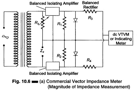
In both parts, the measurement makes use of the equal deflection method, by comparing the voltage drop across the unknown Z to the drop across a standard resistance, with the same current in both.
In the impedance measuring circuit of Fig. 10.6(a), Zx is the unknown impedance and the variable resistance Rs is the standard resistance, which is varied by the calibrating impedance dial. The dial is adjusted until the voltage drops across Zx and Rs are equal. Each voltage drop is amplified in the two sections of the balanced amplifier and applied to each section of a dual rectifier. The algebraic sum of the rectified outputs will then be zero, as indicated by the null reading of the dc VTVM, regardless of the phase angle of Zx since rectified voltage depends only on the magnitude IZI of the unknown Z. This unknown Z, in ohms, is read directly on the dial of the variable standard Rs.
The circuit shown in Fig. 10.6(b) is used for the measurement of phase angle, after the Z balance has been obtained.
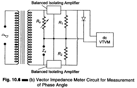
With the switch in the calibration position, the injection voltage is calibrated by adjusting it for full scale deflection on the indicating meter or the VTVM. The function switch is then set to the phase position. In this position, the function switch of the instrument parallels the output of the balanced amplifier, before rectification. The sum of ac output voltages from the amplifiers is now a function of the vector difference between the ac voltages impressed on the amplifiers.
The rectified voltage resulting from this vector difference is shown on the dc VTVM, as a measure of the phase angle between the voltage across Zx and Rs, which are equal in magnitude but different in phase. Thus the meter is able to indicate direct reading values for the phase angle. If required, this angle can be converted to measure the corresponding values for dissipation factor D and quality factor Q.
Where it is necessary to determine the phase angle to a high degree of accuracy, a phase meter is usually employed, e.g. in servos and precise control applications.