Transistor Voltmeter (TVM):
Transistor Voltmeter – Direct coupled amplifiers are economical and hence used widely in general purpose low priced VTVM’ s. Figure 4.9 gives a simplified schematic diagram of a dc coupled amplifier with an indicating meter. The dc input is applied to a range attenuator to provide input voltage levels which can be accommodated by the dc amplifier.
The input stage of the amplifier consists of a FET which provides high input impedance to effectively isolate the meter circuit from the circuit under measurement. The input impedance of a FET is greater than 10 MΩ. The bridge is balanced, so that for zero input the dial indicates zero.
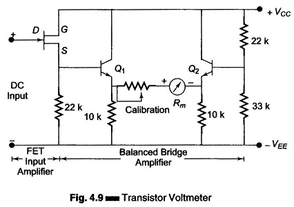
The two transistors, Q1 and Q2 forms a dc coupled amplifier driving the meter movement. Within the dynamic range of the amplifier, the meter deflection is proportional to the magnitude of the applied input voltage. The input overload does not burn the meter because the amplifier saturates, limiting the maximum current through the meter. The gain of the dc amplifier allows the instrument to be used for measurement of voltages in the mV range.
Instruments in the μV range of measurement require a high gain dc amplifier to supply sufficient current for driving the meter movement. In order to avoid the drift problems of dc amplifiers, chopper type dc amplifiers are commonly used in high sensitivity voltmeters.