Average Responding Voltmeter and Peak Responding Voltmeter:
A simplified version of a circuit used in a typical average responding voltmeter is given in Fig. 4.23.
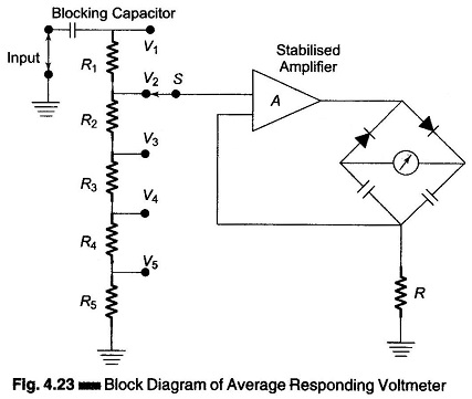
The applied waveform is amplified in a high gain stabilized amplifier to a reasonably high level and then rectified and fed to a dc mA meter calibrated in terms of rms input voltage. In this meter instrument, the rectified current is averaged by a filter to produce a steady deflection of the meter pointer. A dc component in the applied voltage is excluded from the measurement by an input blocking capacitor preceding the high gain amplifier.
The ac amplifier has a large amount of negative feedback, which ensures gain stability for measurement accuracy, and an increased frequency range of the instrument. The inclusion of the meter in the feedback path minimizes the effect of diode non-linearity and meter impedance variations on the circuit performance.
Capacitors in the meter circuit tend to act as storage or filter capacitors for the rectifier diodes as well as coupling capacitors for the feedback signal. The diodes acts as switches to maintain unidirectional meter current despite changes in the instantaneous polarity of the input voltage.
Errors in the reading of an average responding voltmeter may be due to the application of complex waveforms, i.e. a distorted or nonsinusoidal input or the presence of hum or noise.
The accuracy with which an average responding voltmeter indicates the rms value of a wave with harmonic content depends not only on the amplitude of the harmonic but also on the phase.
Peak Responding Voltmeter:
The basic difference between peak responding voltmeters and average responding voltmeters is the use of storage capacitors with the rectifying diode in the former case. The capacitor charges through the diode to the peak value of the applied voltage and the meter circuit then responds to the capacitor voltage.
The two most common types of peak responding voltmeters are given in Figs 4.24 (a) and (b).
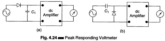
Figure 4.24 (a) shows a dc coupled peak voltmeter, in which the capacitor charges to the total peak voltage above ground reference. In this case the meter reading will be affected by the presence of de with ac voltage.
In Fig. 4.24 (b), an ac coupled peak voltmeter circuit is shown. In both the circuits, the capacitor discharges very slowly through the high impedance input of the dc amplifier, so that a negligible small amount of current supplied by the circuit under test keeps the capacitor charged to the peak ac voltage. The dc amplifier is used in the peak responding meter to develop the necessary meter current.
The primary advantage of a peak responding voltmeter is that the rectifying diode and the storage capacitor may be taken out of the instrument and placed in the probe when no ac pre-amplification is required. The measured ac signal then travels no farther than the diode. The peak responding voltmeter is then able to measure frequencies of up to 100s of MHz with a minimum of circuit loading. The disadvantage of peak responding voltmeters is the error caused due to harmonic distortion in the input waveforms and limited sensitivity of the instrument because of imperfect diode characteristics.