Subtractor using Op Amp or Difference Amplifier Circuit:
Similar to the summer circuit, the subtraction of 2 input voltages is possible with the help of op-amp circuit called subtractor or difference amplifier circuit. The Subtractor using Op Amp circuit diagram is shown in the Fig. 2.31.
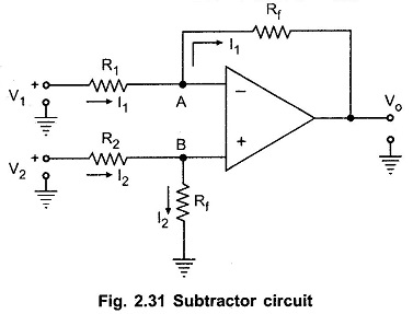
To find the relation between the inputs and output let us use Superposition principle.
Let Vo1 be the output, with input V1 acting, assuming V2 to be zero. And Vo2 be the output, with input V2 acting, assuming V1 to be zero.
With V2 zero, the circuit acts as an inverting amplifier. Hence we can write

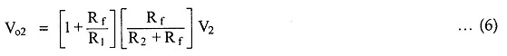
While with V1 as zero, the circuit reduces to as shown in the Fig. 2.32.
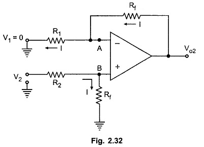
Let potential of node B be VB. The potential of node A is same as B i.e. VA = VB. Applying voltage divider rule to the input V2 loop,
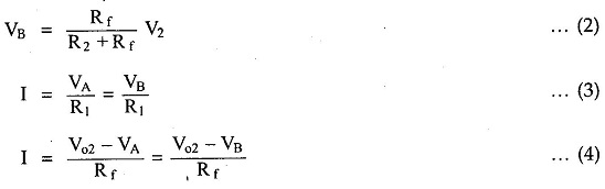
Equating the equations (3) and (4),
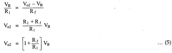
Substituting VB from (2) in (5) we get,
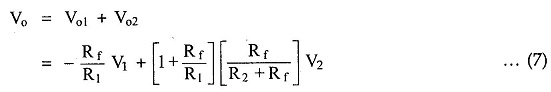
Hence using Superposition principle,
Now if the resistances are selected as R1 = R2,
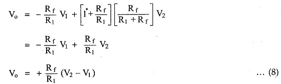
Thus the output voltage is proportional to the difference between the two input voltages. Thus it acts as a Subtractor using Op Amp circuit or difference amplifier.
If R1 = R2 = Rf is selected,
![]()
But by selecting proper values of R1, R2 and Rf, we can have the subtraction of two inputs with appropriate strengths like
![]()