Half Subtractor and Full Subtractor Circuit:
Subtractor are divided into two categories namely, half subtractor and full subtractor circuit.
Half Subtractor Circuit:
The Half Subtractor Circuit consists of four possible elementary operations, namely,
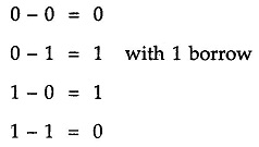
In all operations, each subtrahend bit is subtracted from the minuend bit. In case of second operation the minuend bit is smaller than the subtrahend bit, hence 1 is borrowed. Just as there are half and full-adders, there are half and full-subtractors.
A half subtractor is a combinational circuit that subtracts two bits and produces their difference. It also has an output to specify if a 1 has been borrowed. Let us designate minuend bit as A and the subtrahend bit as B. The result of operation A – B for all possible values of A and B is tabulated in Table 3.8.
Half Subtractor Truth Table:
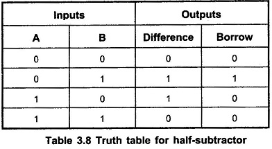
As shown in the Table 3.8, half-subtractor has two input variables and two output variables. The Boolean expression for the outputs of half-subtractor can be determined as follows
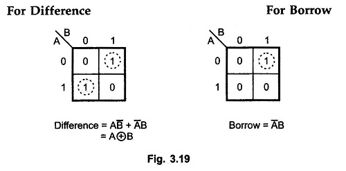
K-map simplification for half-subtractor:
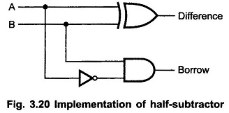
Half Subtractor Logic Diagram:
Full Subtractor Circuit:
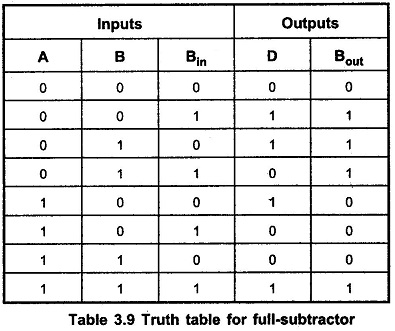
A Full Subtractor Circuit is a combinational circuit that performs a subtraction between two bits, taking into account borrow of the lower significant stage. This circuit has three inputs and two outputs. The three inputs are A, B and Bin, denote the minuend, subtrahend, and previous borrow, respectively. The two outputs, D and Bout represent the difference and output borrow, respectively. The Table 3.9 shows the Full Subtractor Truth Table.
Full Subtractor Truth Table:
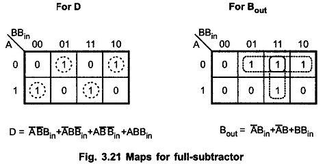
K-map simplification of D and Bout:
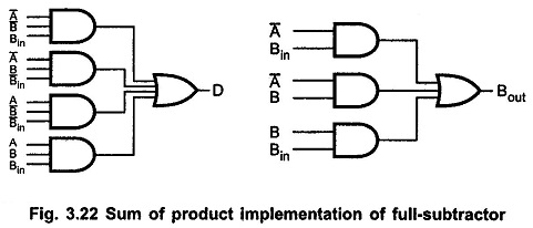
Full Subtractor Logic Diagram:
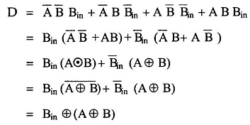
The Boolean function for D (difference) can be further simplified as follows:
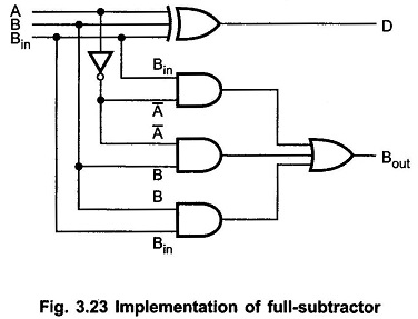
With this simplified Boolean function circuit for Full Subtractor Circuit can be implemented as shown in the Fig. 3.23.
A Full Subtractor can also be implemented with two Half Subtractor and one OR gate, as shown in the Fig. 3.24. The difference output from the second Half Subtractor is the exclusive-OR of Bin and the output of the first Half Subtractor, which is same as difference output of Full Subtractor.
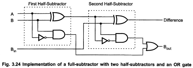
The borrow output for circuit shown in Fig. 3.24 can be given as
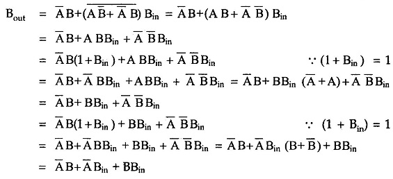
This boolean function is same as borrow out of the Full Subtractor Circuit. Therefore, we can implement Full Subtractor using two Half Subtractor and OR gate.