Systems of Track Electrification AC Electrification System:
As even in single phase electrification, the substations are necessarily required to keep the voltage drop within permissible limits. The type of substations required depends upon the nature of primary supply and system of AC electrification system.
High Voltage AC Supply
Arrangements of power supply to the various electric traction substations in India are as follows:
- Power is purchased from supply authorities who are responsible for the operation and maintenance of 220/132 kV transmission lines and grid substations up to 25 kV outgoing terminals of substations. However, 25 kV feeder circuit breaker is controlled from remote control centre by traction power controller (TPC).
- All the 220/132 kV and 25 kV equipment of substation is owned, installed and maintained by the supply authorities whereas 25 kV circuit breakers are owned, installed, operated and maintained by the railway authorities. This arrangement ends the dual control of 25 kV circuit breakers (operation by railways and installation and maintenance by supply authorities.)
- For better control and expeditious execution of AC electrification system programme Railways considered necessary to own, install, operate and maintain 220 kV/132 kV equipment at the substation themselves. The Railway authorities take high voltage supply of 220 kV/132 kV at the substations from the supply authorities. This arrangement exists on Madras-Villupuram, Rourkela-Durg and Virar-Sabarmati sections.
- In another arrangement 220/132 kV 3-Φ supply is taken at one point from the supply authorities and then it is distributed by the railway authorities to different traction substations through their own transmission lines as in case of Kanpur-Tundla section.
Power Supply Arrangement for AC Electrification System
As mentioned already, electric power is taken from grid supply at 220/132 kV and then stepped down to 25 kV single phase at traction substations through step-down transformers and suitable switchgear. The electric power at 25 kV ac is transmitted to feeding posts through feeders. Feeding posts are located opposite the track. At feeding posts, this power is fed to OHE above track for traction work. The power supply arrangement is described in details in the forthcoming sub-articles.
Sectioning Arrangement For Power Feeding
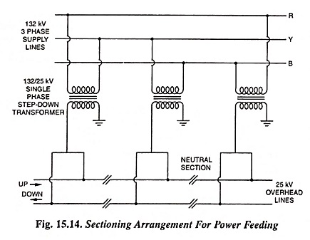
Power is generated and transmitted, by supply authorities, by 3-phase system and it is distributed in such a way that the loading of all the three phases remain almost same. Unbalanced loading of the three phase system results in phase shift and also causes rotor heating of alternators. Electric traction is a single phase load so in order to avoid unbalanced loading consecutive substations are supplied by different phases in rotation as depicted in Fig. 15.14. In dc track electrification, all the substations feed OHE in parallel but in AC electrification system, section supplied by one substation works as an independent unit and never work in parallel. As different sections fed by different substations work on different phases, a neutral section is provided approximately in the middle of two feeding posts. The purpose of providing neutral section is to isolate the two sections supplied by different phases. Thus, the pantograph of the locomotive does not bridge two different live phases of 25 kV supply while passing from one section to another one.
Substations
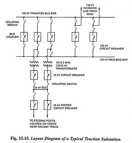
Figure 15.15 depicts the layout diagram of a typical traction substation. Traction substation is supplied by 220/132 kV ac supply either from two sources of supply or by double circuit 220/132 kV transmission line for the sake of reliability of supply. For rapid clearance of fault(s) occurring on transmission line or substation suitable protective equipment is provided. Two sets of 220/132 kV , bus-bars (one main bus-bar and other transfer bus-bar) are provided in each substation. Both of these bus-bars are connected through bus coupler circuit breaker. The incoming and outgoing transmission lines are connected to both the bus-bars through the circuit breakers, as shown in Fig. 15.15. With such an arrangement of the two bus-bars and isolators on both sides of circuit breakers continuity of supply can be maintained while doing maintenance work on any bus-bar or circuit breaker on primary side of transformer. Normally two single phase transformers of rating 10 or 12.5 MVA, 132/25 kV are installed in a traction substation. Of the two transformers only one will be in operation normally, the other one acting as standby. Output voltage at 25 kV is maintained within -5% to +10% with the help of tappings provided on the transformer.
One 25 kV transformer circuit breaker and one 25 kV feeder circuit breaker equipped with an overload relay and an impedance relay are provided on the output side of transformer for clearance of all faults on OHE. One terminal of 25 kV winding of transformer is connected to earth solidly at substation and return feeders from all the rails of electrified track opposite to feeding post are also connected to this earthed end solidly. Provision of 25 kV bus-bar on the output side facilitates the maintenance of any transformer or its associated circuit breaker without any interruption of power supply. These substations are unattended type and are controlled by remote control operation. Spacing of these substations are 50 to 90 km and they are located closed to feeding posts, maximum distance being 2 km.
Feeding Post
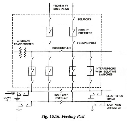
Figure 15.16 depicts the layout diagram of feeding post. It is located opposite the electrified track on towers. Two 25 kV incoming feeders from traction substation are connected to two sets of bus-bars in feeding post through circuit breakers. The circuit breakers are controlled from a remote control centre of the railway. Each feeder consists of two conductors, one insulated for 25 kV connected to the bus-bar and the other insulated for 3 kV connected to the track for return currents. Two sets of feeders and bus-bars along with one bus coupler make it possible to maintain continuity of supply in case of fault or carrying out maintenance work on any feeder or circuit breaker. In the case of two track lines there are four interruptors, two for each feeder and feeding two tracks on one side of feeding post only. Interruptors are single pole, low oil content outdoor type oil switches and are meant for connecting different sections of OHE to feeding post. Interruptors are normally arranged for remote control operation but can also be operated manually locally in case of emergency. Interruptors are not supposed to clear faults automatically like circuit breakers as these are not provided with any protective relays. These are supposed to operate (open or close) in normal load conditions only.
One auxiliary transformer of rating 25 kV/230 V, 10 kVA is also installed for 230 V supply at feeding post for charging batteries. Batteries are installed for providing uninterrupted power supply for remote control equipment, signaling and lighting circuits.
Sectioning and Paralleling Post
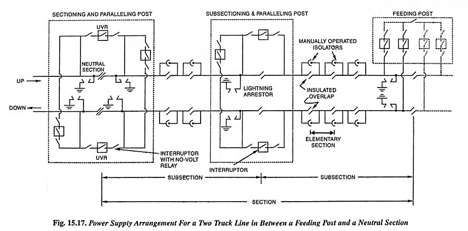
Zone covering up and down tracks between feeding post and neutral section is called one section and so each feeding post supplies two sections. The supply to each section is controlled by a circuit breaker. Figure 15.17 illustrates the power supply arrangement for a double track line in between a feeding post and a neutral section. Two adjacent sections supplied by different substations are connected through neutral section to avoid bridging of different phases of supply by pantograph. In case of failure of supply from one substation, supply is extended to it by adjacent section through two bridging interruptors—one for each track provided in sectioning and paralleling post. These posts also consists of two paralleling interruptors to parallel OHE of up and down tracks, one on each side of neutral section. The bridging interruptors remain normally open and are closed in case of emergency only. Bridging interruptors are provided with no-volt relay to avoid short circuiting of two different live phases. These are closed after giving warning to driver to drop the pantograph while passing in front of feeding post to which supply is extended. This precaution is necessary because no neutral section is provided in front of a feeding post except only an insulated overlap.
Subsectioning and Paralleling Post
Each section is subdivided into two or more sections by sectioning and paralleling posts, normally at a distance of every 10 to 15 km, so as to isolate the faulty section. Each subsectioning and paralleling post consists of two interruptors for bridging adjacent subsections and one interruptor for paralleling up and down tracks.
Sometimes only subsectioning post is provided and so there is no interruptor for paralleling up and down tracks. This is provided very rarely.
At some stations with large yards, change-over switches are sometimes provided so that the supply may be derived either from OHE of one section or the other. Normally, it is locked in one position but in an emergency it can be changed over after taking necessary precautions.
Elementary Section
Each subsection is further divided into elementary sections of length approximately 1 km so as to ensure rapid isolation of fault on OHE and facilitate maintenance work. Two adjacent elementary sections are separated by insulated overlap bridged by isolators, which are manually operated on no load.
Block Diagram of an AC Electric Locomotive
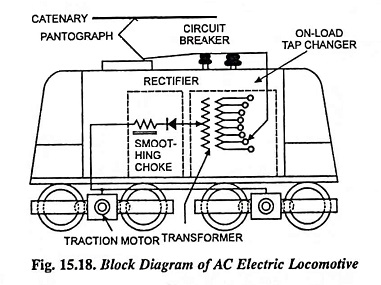
Block diagram of an ac electric locomotive is depicted in Fig. 15.18. It collects current from overhead equipment (OHE) by means of a pantograph collector which usually carries a sliding shoe for contact with the overhead trolley wire. The locomotive essentially consists of (i) air circuit breaker (ii) on-load tap changer (iii) step-down transformer (iv) converting machinery (v) smoothing chokes and (vi) dc traction motors.