Electrical Drive Systems:
Each Electrical Drive Systems is different from other Electrical Drive Systems. However, there are some common features associated with all Electrical Drive Systems. To understand them it is good enough to consider few examples. This approach has been adapted here.
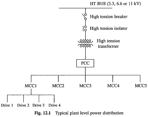
Normally, a Electrical Drive Systems receives its incoming ac supply from a Motor, Control Centre (MCC). MCC controls the power to few Electrical Drive Systems located in an area. In a large manufacturing plant, many such MCCs exist. These in turn receive the power from the main power distribution centre called Power Control Centre (PCC). Fig. 12.1 gives a typical layout of a plant level power distribution network. MCC and PCC normally use air circuit breakers as the power switching elements, with ratings up to 800 V, 6400 A maximum. Overloads are protected by the thermal overload relays. The short circuit protection is offered through the magnetic sensing/release mechanism of the breaker itself. HRC fuses are provided for the back-up protection as well as for protection against the faults occurring in the bus bar sections before the breaker.
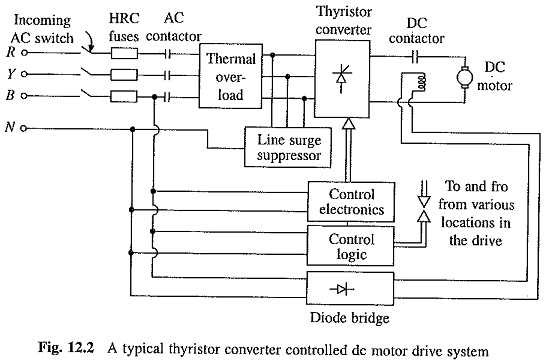
As examples, two Electrical Drive Systems are being considered here. One employs converter controlled dc motor and other inverter fed ac motor.
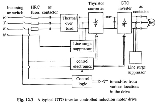
These Electrical Drive Systems, shown in Figs. 12.2 and 12.3 respectively, consist of the following parts:
- Incoming ac switchgear.
- Power converter and/or inverter assembly.
- Outgoing DC or AC switchgear.
- Control logic which implements drive’s interlocking and sequencing requirements with the help of relays and contactors or programmable logic controllers (PLCs).
- Motor and the associated load.
Incoming ac Switchgear: This consists of a switch-fuse unit and an ac power contactor, the rating of which range upto 660 V, 800 A. Beyond these ratings, air circuit breakers without magnetic release are commonly used as incoming switches and normal contactors are replaced by the bar mounted contactors. These contactors can increase the range up to 1000 V, 1200 A. The fuses used are HRC fuses (ratings available up to 1000 V, 800 A). Thermal overloads are incorporated for taking care of abnormal overloads but not short circuits. Moulded case circuit breakers (ratings 660 V, 800 A maximum) are sometimes used to replace the contactors.
Power Converter and/or Inverter Assembly: This has two major blocks—Power and Control Electronics. Power Electronics block consists of semiconductor devices, heat sinks, semiconductor fuses, surge suppressors, cooling fans (if used for forced cooling of converters). Control Electronics consists of triggering circuit, its own regulated power supply, and driving and isolation circuits to control and regulate the power flow to the motor. If the drive operates in a closed-loop, it also will have controllers (or compensators), and current and speed feedback loops. In drives employing semiconductor converters, it is now common practice to incorporate circuits to monitor the health of various converter modules, electronic cards and protections, such as overcurrent, overvoltage, overspeed, single phasing, and standstill and stall condition protections of the motor. In case an application demands any additional facilities like reference conversion (e.g. 0 to 10 V reference converted to 4 to 20 mA reference) or availability of signal monitoring at some other location, such facilities are then built up in control electronics. Generally, control electronics has a three port isolation, i.e. its power supply, inputs and outputs are galvanically isolated with adequate insulation level (usually 2.5 kV for a 415 V system voltage).
Line Surge Suppressors (LSS): These are used to protect the semiconductor converter against voltage spikes produced in the line due to on and off switchings of loads connected on the same line. The LSS along with the line inductance (normal requirement is 3% line impedance) blocks the voltage spikes. It also isolates the supply from the notches generated due to thyristor commutations. It also absorbs (depending upon the design but generally 50%) certain amount of trapped energy when the incomming circuit breaker operates and breaks the current supplied to the drive. LSS will not be required when the power modulator is not a semiconductor converter.
Control Logic: Control logic is required in order to achieve interlocking and sequencing of various operations of the Electrical Drive Systems under normal, fault and emergency conditions. The interlocking protects the system against abnormal and unsafe operations. The sequencing ensures that various drive operations, such as starting, braking, reversing, jogging etc., are carried out in a preplanned sequence so that the coupled load is driven in a desired manner and the drive capabilities are put to optimum use. In a simple drive system, interlocking and sequencing are realised with the help of relays and contactors. When the interlocking and sequencing operations are complex, these are implemented using programmable logic controllers (PLCs).
In order to appreciate the interlocking and sequencing operations, let us deviate from the Electrical Drive Systems of Figs. 12.2 and 12.3 and consider the drive circuit shown in Fig. 12.4 for low voltage automatic starting of an induction motor using auto-transformer starter with closed circuit transition. Start and stop are push button switches. Circuit employs three contactors, coils of these are marked M, lC and 2C. The contacts of these contactors are denoted by M1,M2,M3 and M4 IC1, IC2 and 1C3, and 2C1,2C2 and 2C3 respectively. Symbol denotes normally open contact, which gets closed when the contactor operates and denotes normally closed contact, which opens when the contactor operates. Circuit uses time delay relay TDR having normally closed and open contacts TDR1 and TDR2, respectively. Time delay relay operates at a fixed time after its coil TDR receives excitation. Circuit implements autotransformer starting with closed circuit transition in the desired sequence in the following manner:
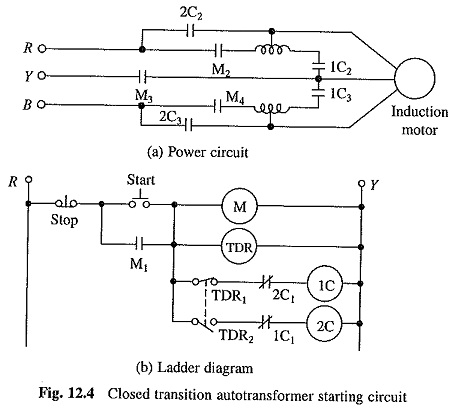
When start push button is pressed, coil of contactor M is energised and contacts M1,M2,M3 and M4 are closed. Simultaneously, coil of time delay relay TDR is also energised, initiating its operation. Closing of contact M1, energise the coil of contactor 1C, and contacts 1C2 and 1C3 are closed, and 1C1 opens. Motor is connected to reduced voltage and accelerates. Releasing pressure on the push button ‘start’ will make no difference because the contact M1, in parallel to it, is already closed. Time delay relay TDR operates at a fixed interval after its coil is energised. Consequently, contact TDR1 opens and TDR2 is closed. Opening of contact TDR1 de-energise contactor 1C, opening contacts 1C2 and 1C3, and motor gets connected to the supply with reactors in series with two phases and third phase directly across the supply. De-energisation of contactor lC also closes the contact 1C1. Since TDR2 is already closed, contactor 2C gets energised, closing contacts 2C2 and 2C3, and thus, motor is connected to the full voltage. Pressing of ‘stop’ push button will disconnect motor and control circuit from the supply.
Note that with pressing of push button ‘start’, motor starts automatically in the desired sequence. Further, operations of contactors IC and 2C are also interlocked so that transition from low voltage to full voltage is done with closed circuit transition. Diagram of Fig. 12.4, which indicates various switching functions is known as the industrial ladder diagram or simply ladder diagram.
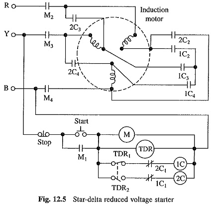
Ladder diagram of Fig. 12.5 shows another example of interlocking and sequencing operation. Circuit implements the star-delta starting method of induction motor with open circuit transition. Reader is advised to work out the operation of the circuit.
We now come back to the drives of Figs. 12.2 and 12.3. The dc drive of Fig. 12.2 needs, for its protection, interlocking such that the drive will not be operated unless following conditions are met:
- dc motor field is energised to its rated value.
- Semiconductor fuses connected in the converter to protect its thyristors are all healthy.
- Thermal overload relay in the incomming supply has not operated.
- MCCB (if any) in the incomming supply has not operated.
- Overvoltage and overcurrent sensing circuits or relays have not operated.
- Converter cooling fan (if used for forced air cooling) is under proper running condition.
- Speed signal (coming from the speed sensor) loss circuit has not operated; this interlocking is required only when the drive has closed loop speed control.
- Supply is healthy and no single phasing has occurred (single phasing sensing circuit or relay has not operated).
- Cards of control electronics are all healthy.
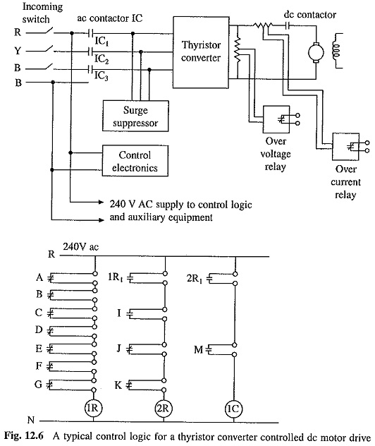
Drive will be ready for normal operation when the above conditions are satisfied. The implementation of these interlocks is shown in Fig. 12.6. A is the normally open contact from the field supply sensing relay. It will be closed when field is energised. Contacts B to G are normally closed contacts from the semiconductor fuses of thyristor converter. When all fuses are healthy, all these contacts are closed. When field is energised and all fuses are healthy, the relay 1R will be energised closing its normally open contact 1R1. I is the normally open contact of cooling fan air flow switch which gets closed when the fan is running and has an adequate velocity. Contacts J and K are normally closed contacts of overcurrent and overvoltage relays. When contacts 1R1, I, J and K are closed, the coil of relay 2R is energised and its normally open contact 2R1 gets closed. If control cards are all healthy, normally open contact M will be closed. When 2R1 and M are closed, the main contactor IC will be turned on and its contacts IC1, IC2 and IC3 will be closed. Converter will receive three-phase supply and the drive will be ready for normal operation.
When start command is given through push button, motor brakes will be released, dc contactor will close and motor will start.
When a drive which is running normally enters a fault mode, one or More interlocks mentioned above operate and steps are taken to stop the drive operation.
In addition to interlocking, proper sequencing will be required to carry out following operations:
- Running of motor (at desired or set speed) under normal operating conditions, in both forward and reverse directions.
- Stopping of motor under normal stop command.
- Stopping of motor under fault condition when any of the interlocks mentioned above operates.
- Stopping of motor deliberately when emergency conditions prevail.
For a single machine drive system, control logic controls the operations relevant only to the Electrical Drive Systems. However, in case the process demands, it may accept few interlocking and sequencing signals provided externally. Extrusion pump, printing machine and lift control are few examples of single machine drives. For a multi-machine drive system, control logic controls the operations required by individual drives as well as synchronization amongst all the drives. It also accepts few interlocking signals provided externally. Few examples of multi-machine drives are, cold rolling mill, bar mill and paper mill.
Usually control logic of a single machine drive system can be implemented using few relays and contactors. However, for multi-machine drive systems, the complexity of interlocking and sequencing increases considerably. The hard wired relay-contactor logic becomes bulky and puts constraint on the changes required to be carried out later. Under such situation, a programmable logic controller (PLC) is used.
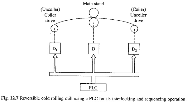
Figure 12.7 shows a block schematic of a cold rolling mill multi-machine drive using PLC. It will be beyond the scope of this book to describe complete operation of the drive. However, conceptual understanding of the importance of interlocking and sequencing operations can be obtained by a brief discussion of the Electrical Drive Systems. The purpose of cold rolling mill is to roll steel strip to reduce its thickness to a desired level. The steel strip wound in a mandrel is received from a hot strip mill. This mandrel driven by drive D1 feeds the rolling mill while another driven by D2 rolls the strip on it as it comes out of the rolling mill. When D2 operates in motoring mode, D1 operates in braking, such that the strip moves at a constant speed with constant tension. Mill rollers are driven by the main drive D. In first pass a predetermined distance is adjusted between rolls. Initially the drive is accelerated smoothly to desired speed, and then rolling process is carried out at constant strip tension and speed. Drive D2 operates under motoring and D1 under braking. Mandrel coupled to D1 unrolls and coupled to D2 rolls the strip. When first pass is completed, the drive is decelerated smoothly to standstill. Now metal strip is fully rolled on the mandrel coupled to D2. To start second pass, distance between rollers is reduced to a preset value. Now, drive is smoothly accelerated in reverse direction to fully speed with D1 motoring and D2 braking. The rolling is carried out at constant speed and constant strip tension. When second pass is completed, the drive is decelerated smoothly to standstill. This way strip is rolled to the required thickness through several passes.
PLC here interlocks and sequences the operation of three drives, namely, mainstand D, coiler D1(D2) and uncoiler D2(D1) so that the rolling process is carried out in a predetermined manner. PLC is a microprocessor based circuit and uses 8 or 16 bit microprocessor for its CPU depending on functional capability required. PLC can be programmed to remember settings of various drives, speeds, tensions, number of passes etc. depending upon the metal quality, thickness and ultimate reductions required. These require on-line changes, which are difficult to realise with relay-contactor logic alone.