DC Standard Differential Voltmeter:
A basic DC Standard Differential Voltmeter can be operated in different modes. The three basic modes of operation are
- as a dc voltage standard,
- as a dc differential voltmeter, and
- as a dc voltmeter (conventional).
1. DC Voltage Standard:
A + 1 V dc stable supply is obtained from a temperature controlled reference supply, which is applied to a decimal divider network. With the help of switches on the front panel of the voltmeter, the divider ratios can be controlled (varied), allowing the reference supply to be adjusted in steps of 1 μV each, from 0 to 1 V. A low level dc amplifier is used to amplify the low level voltages obtained from the decimal divider to a sufficient level. This reference output voltage is then applied to a high gain dc amplifier with positive feedback to obtain precisely controlled gain characteristics.
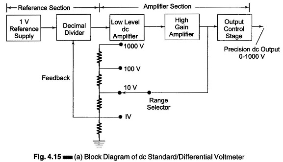
Figure 4.15 (a) illustrates the standard mode of operation. In the standard mode of operation, the differential voltmeter is used to provide a standard reference source in the laboratory, where the instrument generates a precision output voltage from 0 — 1000 V as a reference source.
The dc amplifier consists of several stages in cascade, providing an open loop gain (A) of 10 or higher. (The feedback network monitors the actual output voltage and feeds a controlled fraction of the output back to the amplifier input.)
The closed loop gain of the feedback amplifier is given by

where
- G = closed loop gain (voltage gain with feedback)
- A = open loop gain (voltage gain without feedback)
- β= fraction of the output used as degenerative feedback
If the open loop gain is very high and A β is much greater than 1, G = 1/β implying that the gain of the amplifier depends only on the amount of degenerative feedback.
From the equation (G = 1/β), it can be seen that as β decreases, the closed loop gain of the amplifier increases. The value of β in turn depends upon the accuracy of the voltage dividers used, i.e. the precision value of the resistors used for the voltage dividers (wire wound precision resistors). The following ranges of standard voltage are available at the output.
0 – 1 V in 1 μV steps (1 V range)
0 – 10 V in 10 μV steps (10 V range)
0 – 100 V in 100 μV steps (100 V range)
0 – 1000 V in 1 mV steps (1000 V range)
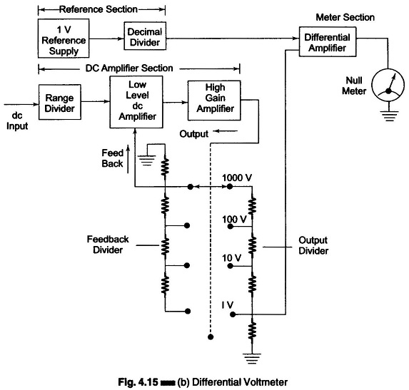
2. DC Differential Voltmeter:
The unknown dc voltage is applied to the input of the amplifier section and a part of the output voltage is fed back to the input stage with the help of one divider network, which controls the closed loop gain of the amplifier. The other section of the voltage divider network applies a fraction of the output voltage to the differential input of the meter amplifier.
The meter circuit measures the difference between the feedback voltage and the reference voltage, indicating a null deflection when the two voltages are equal. The range selector (on the front panel) controls both the feedback voltage and the voltage that is applied in opposition to the reference divider output, such that 1 V capacity of the reference supply is never exceeded.
A differential voltmeter is shown in Fig. 4.15 (b).
3. DC Voltmeter:
In this mode of operation the instrument is connected as a dc voltmeter. High input impedance to the unknown voltage source is provided by the dc amplifier, which act as a buffer stage.
The input voltage is amplified and the dc output voltage is applied directly to the meter circuit. The meter circuit involves a feedback controlled amplifier and allows a selection of the sensitivity.