Linear Resistance Damping:
By introducing a linear resistance across the circuit breaker during interruption, the restriking transients are damped. Provision has to be made for subsequent interruption of the resistance circuit. Two such ways are shown in Fig. (15.27). In Fig. (15.27a) the resistor R is switched into circuit by the breakdown of the ionized exhaust that are blown from gap No. 1 to gap No. 2. Immediately after gap No. 1 has ceased to carry current, gap No. 2 is still fed by hot ionized air which causes it to be broken down by the restriking transient in preference to gap No. 1. At the next current zero gap No. 2 is fed with cold unionized air and the resistor current is in turn broken. In Fig. (15.27 b) the arc in the shunted gap No. 1 is extinguished first and the resistor then shunts L and C until the arc carrying the resistor current in gap No. 2 is extinguished. By this time the restriking voltage transient decays down.
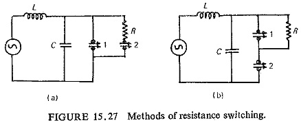
It will thus be noted that the voltage transient encountered on finally clearing the circuit is impressed on gaps 1 and 2 in parallel in case of Fig. (15.27a) and on gap No. 2 only in case of Fig. (15.27b).
For capacitive current breaking and current chopping gap No. 1 can be proportioned solely to clear the rated breaking capacity current and no thought need be given to the electric strength which the gap attains. In practice it is found that arrangement (a) is most suitable for breakers of 33 KV and below whilst arrangement (b) is most suitable for 66 KV and above. This is because for voltages up to 33 KV high restriking rates may be associated with the maximum fault MVA likely to be experienced. This differs from the conditions found on higher voltage networks where coupled lines tend to reduce the RRRV at large fault MVA.
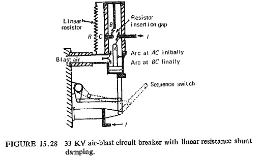
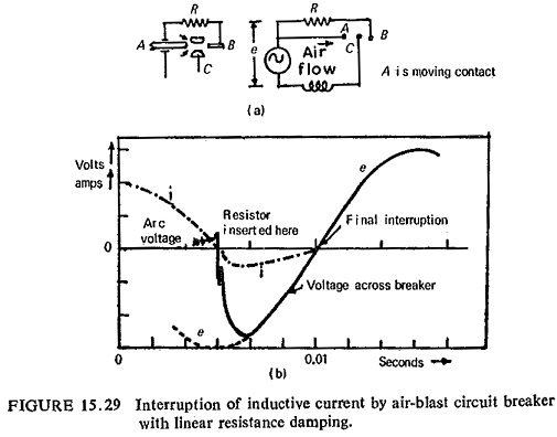
Figure (15.28) shows diagrammatically, linear resistors applied to an air-blast circuit breaker incorporating arrangement (a) and Fig. (15.29) shows the current voltage curves for inductive current interruption. However, on high voltage systems such as 132/400 KV, the use of shunt resistors in case of forced blast oil or air-blast circuit breakers is of little importance. In this case the RRRV/MVA characteristic can be obtained with designs which can cope with ordinary conditions of service. Nevertheless shunt resistors are used at times because of other considerations as mentioned earlier. Though such a use of resistors results in reduced duty on the main interruptors, the additional apparatus required for the interruption of resistor current tends to increase the complication of the complete forced-blast circuit breaker. In all cases where shunting resistors are used auxiliary contacts to break the residual current must be provided. In case the current exceeds 200 A, the auxiliary contacts themselves must have some form of arc extinguishing blast.
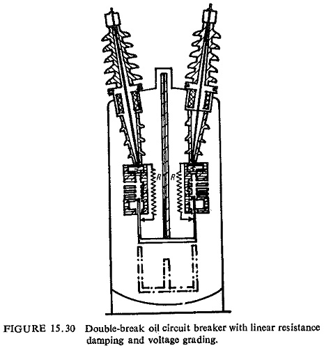
For self-blast oil circuit breakers, the most onerous duty with respect to RRRV and voltage peak tends to occur at relatively low fault values, of the order of 10 to 30% of the breaking capacity. Under these conditions, pressure in the arc-control device is low at the time when high system RRRV is associated with 100% recovery-voltage peak. This is overcome by connecting linear resistance in parallel which will pass sufficient current to limit the RRRV. However if the sensitivity of the design is attributable more to restriking voltage peak than to RRRV, account must be taken of the values of system constants when transmission lines of large capacitance are coupled. With such designs and when the capacitance is large, much larger shunt currents (increased in the ratio √C) are required to ensure critical damping. Figure (15.30) shows a two-break circuit breaker, shunted by linear resistors, interruption of the fault current occurs during the initial part of contact travel. Continuation of the contact travel interrupts the shunt current in the isolation gap outside the pot throats, but in this case without additional complication.
The shunt resistor absorbs electrical energy and converts into heat energy during small inductive current interruption when overvoltage oscillations are produced by current chopping.
The shunt resistor prevents restrikes or limits their number during capacitive current interruption, as illustrated in Fig. (15.31). The resistor current must however be so proportioned that overvoltage surges are not produced when the resistor current itself is interrupted, and this implies an upper limit to the current that can be permitted.