Linear, Logical Address and Physical Address in Microprocessor:
The Linear, Logical Address and Physical Address in Microprocessor is given below
Physical Address
In protected mode, the Intel Architecture (IA) 32-bit processors/Pentium processors provide a usual physical address space of 232 bytes or 4 Gbytes. Therefore, the processor can address up to 4 Gbytes memory locations through its address bus. This 4 Gbytes address space is a basic flat model of memory and these address spaces are unsegmented. The address range or memory map of 4 Gbytes address space is from 00000000H to FFFFFFFFH.
The memory mapping divides the 4 Gbytes physical memory into different segments and pages. When paging technique is used for memory management, the paging unit takes the output of the segmentation unit, which is called the linear address, and subsequently converts the linear address into a physical address. If paging is not in use, the linear address simply maps directly onto the physical address.
Logical and Linear Addresses
During protected mode, the segmentation unit generates a linear address from a logical address. Each byte which is stored in the processor’s address space, can be accessed with a logical address. The logical address consists of a 16-bit segment selector and a 32-bit offset as depicted in Fig. 12.17. The segment selector is used to identify the segment descriptor which provides the base address of the segment. The offset specifies the location of the byte in the segment relative to the base address of the segment. The segment descriptor has a limit field. When the linear address is outside the size of the segment, an exception will be generated. Hence, the segments will be protected from invalid accesses.
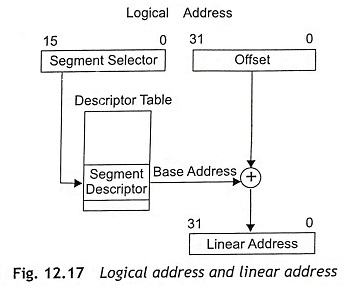
A linear address is a 32-bit address in the processor’s linear address space. Just like the physical address space, the linear address space is also a flat memory model and it is unsegmented. The linear address space consists of all the segments and system tables which are used to define a system. The linear address space is 232 bytes or 4 Gbytes of address spaces. The address range of linear address spaces is from 00000000H to FFFFFFFFH. The IA-32 bit Pentium processors convert each logical address into a linear address. There are three steps to translate a logical address into a physical address.
Step 1 Find the index field from the segment selector and the use the index field to locate the segment descriptor for the segment in the Global Descriptor Table (GDT) or Local Descriptor Table (LDT). This step is required in the processor whenever a new segment selector is loaded into a segment register.
Step 2 After that, test the access and limit fields of the descriptor to make sure that the segment is accessible and the offset is within the limits of the segment.
Step 3 The base address of the segment will be obtained from the segment descriptor. Then the base address of the segment will be added to the offset to determine a linear address.
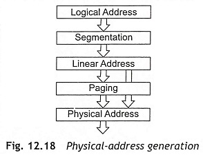
When the paging is not used in the system, the processor maps the linear address directly to a physical address. Therefore, the linear address directly placed on the processor’s address bus when paging is not used. If the paging is incorporated in the linear address space, a second level of address translation is used to translate the linear address into a physical address. Figure 12.18 shows the physical address generation from logical and linear addresses.
Segment Registers or Segment Selectors
In protected mode, the segment registers or segment selectors consist of index filed, table indicator and RPL (Requested Privilege Level) as depicted in Fig. 12.19. The segment registers are used as segment selectors rather than segment base addresses.
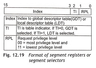
The index field (bit 15 to bit 3) is used to locate into the current table of segment descriptors. IA-32 Pentium processors can hold segment descriptors either in a Global Descriptor Table (GDT) or in a Local Descriptor Tables (LDT).
The Table Indicator (T1) field or bit 2 of the segment selector decides which table to be used. When TI = 0, the Global Descriptor Table (GDT) is selected. If TI = 1, the Local Descriptor Table (LDT) is selected. Actually, GDT and LDT are in the processor’s linear address space. The LDTR (Local Descriptor Table Register) and GDTR (Global Descriptor Table Register) hold the base addresses for the local and global descriptor tables respectively.
The Requested Privilege Level (RPL) bits ‘1’ and ‘0’ are used to find out the privilege level of a program which must be accessed by the segment. These bits are called the current privilege level and these bits are used to define the privilege level of the currently active program. There are four different privilege levels (PL) from 0 to 3. The privilege level ‘0’ has the highest priority and the privilege level ‘3’ has the lowest priority.
Application programs with lower privilege levels can only access a segment; whereas programs with a higher privilege level, by using special gates, can access to higher privilege segments. The Operating System (OS) or kernel has the highest privilege level as PL = 0 and application programs have the lowest privilege level as PL = 3. For example, the instruction LGDT (Load Global Descriptor Table) can only execute when the current program has a privilege level ‘0’.
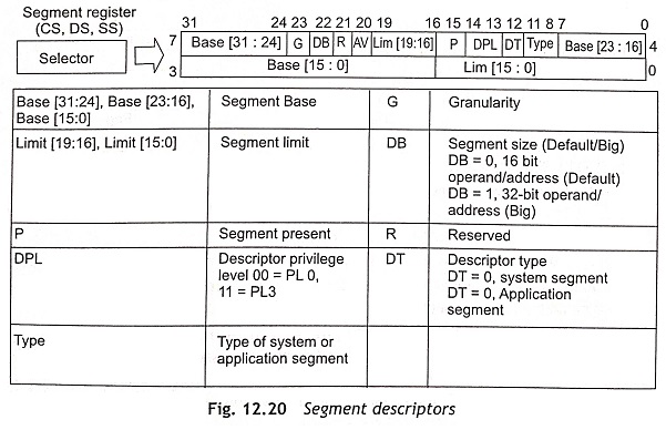
Global and Local Descriptor Tables and Cache Registers
The global descriptor table (GDT) is a list in memory which describes the segment sizes and addresses in memory in terms of segment descriptors. Each segment descriptor has 8 bytes as shown in Fig. 12.20. The global descriptor table holds segments available to all tasks, but the local descriptor table (LDT) is only available to the currently active task. The segment descriptor provides the 32-bits segment base address (Base [31:24], Base [23:16], and Base [15:01]) and 20-bits limit (Limit [19:16] and Limit [15:0]) for the size of the segment. The function of other fields of the segment descriptor are given in Fig. 12.21. The 20-bits of the limit field can be used to represent either a memory size of up to 1 MByte or up to 4 GByte, depending on the granularity (G) bit. When G = 0, byte granularity means that the 20 bits represent 1 Mbyte. If G = 1, the granularity is 4K in size and it represents 20 bits x 4K = 4 Gbyte. The DB bit is used to make instructions as either 32-bit instructions or 16-bit instructions. For example, a 32-bit instruction is mov eax, mem32 when DB = 0 and a 16-bit instruction is mov ax, mem32 if DB = 1.
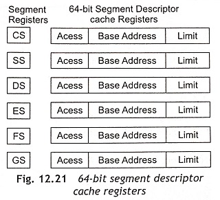
During accessing memory, if the processor does not want to use the descriptor tables frequently then the processor loads the base address and limit for a given selector into a cache register which is associated with each selector. Figure 12.21 shows the 64-bit segment descriptor cache registers. Whenever the contents of a segment register change, the local descriptor table (LDT) or global descriptor table (GDT) is accessed for the base address and limit. After that, the base addresses and limits are placed in the segment descriptor cache register. Subsequently, the cache register is used for the base addresses and limits.
Interrupts in Protected Mode
In protected mode of IA 32-bit Pentium processors, the interrupt vector table is an Interrupt Descriptor Table (IDT). The interrupt descriptor table works in the same way to the segment descriptors. The IDT is able to hold up to 256 interrupt levels. However, each interrupt level can be accessed through a interrupt gate rather than an interrupt vector.
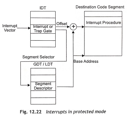
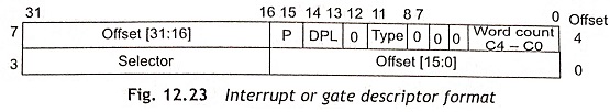
Usually, the interrupt type number is located at the interrupt descriptor table. The IDT may be located anywhere in the memory system where the first 1K hold the interrupt vectors as depicted in Fig. 12.22. The content of IDT is interrupt or trap gate. The format of an interrupt or gate descriptor is shown in Fig. 12.23. The segment selector is used to locate segment descriptor on the global descriptor table or the local descriptor table and generates base address. The base address and offset are combined to find interrupt procedure at the destination code segment.
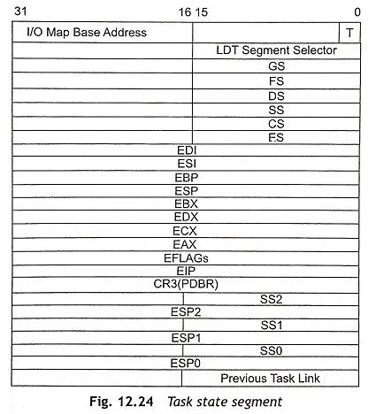
Task State Segment (TSS)
The task state segment descriptor consists of information about the location, size and privilege level of the task state segment. Usually, the task state segment is described by the TSS descriptor and it does not contain code or data. Actually, the TSS holds the state of the task and linkage so that tasks may be nested during operation. Figure 12.24 shows the task state segment.