Influence of Static Protective Relays:
Influence of Static Protective Relays on the associated equipment like current transformers, voltage transformers, etc,. Let us discuss one by one.
Current Transformers:
Burdens on current transformers have a great influence on their design and for a long time the problems of transient performance have given way to a progressive reduction of the relay burdens. However, due to increased fault levels, primary time constants and protection sensitivity requirements, the size of C.T.’s has not been decreased substantially. Added to this in e.h.v. substations, the increased length of interconnected leads complicates the problem. The reduced burden of static relay is such as to be small compared to the burden of secondary winding and its interconnecting leads. The reduction of size and/or increased performance entails relays to be mounted on or close to the switch gear. Thus with Influence of Static Protective Relays, the stress will be on optimum transient C.T. performance with a short-circuited secondary winding. A single C.T. could perform all protection duties and this approach may be justified up to 33 kV or 66 kV where accommodation of C.T.’s affects the size of the switch gear, but at the tiny. levels, separate C.T.’s will still be justified for reasons of security.
Linear couplers, as a means of overcoming problems of transient response, have riot yet gained wide acceptance their inductive nature nd low signal levels being the main limitations. New methods of obtaining current signals, c.g optical links, are being investigated and are practical with Influence of Static Protective Relays.
In one technique an ordinary instrument C.T. is used and the secondary current controls a pulse coding device which sends luminious, acoustic or radio signals to a receiver at earth potential. The most successful one uses a laser light beam transmitted by fibre optics. In this arrangement the pulse coding device modulates a gallium arsenide laser and the coded light pulses travel through a 6 mm-diameter bundle of 50000 glass fibres to a light receiver where the pulses are decoded, amplified and sent by trine cable to the meters and relays. The fibre glass bundle is very flexible so that it can follow a convenient path,, e.g. through an insulator to the breaker mechanism cubicle. This arrangement gives the required e.h.v. insulation and has low light loss. It is immune to interference and has a voltage output so that relays and meters can be connected in parallel rather than in series. For maximum reliability two laser C.T.’s are used so that if one fails, the burdens can be be automatically transferred to the other, in less than 2μ seconds time.
Voltage Transformers
Here again, the size of a V.T. has almost no relation to the actual relay burdens connected to it. In certain cases the V.T. used may be rated for 150 VA while the complete static distance protection connected to it may impose a burden of only 1.5 VA. The size of voltage transformers (both electromagnetic and capacitive types) could be reduced consistent with the reduced burdens of static relays, or the application practice could be modified.
The capacitive voltage transformer at present considered economical only at e.h.v. levels, could become economical at lower voltages and may also use the relatively low capacitance integral in the switch gear like bushings, etc. For transmission (e.h.v.) voltages, the problem of transient response of capacitor V. T.s will be specially taken care of by faster protection and this is facilitated by the low reactive power requirements of static relays. Attempts are under way to obtain bus bar voltage signals for synchronizing by using air-spaced capacitance probes.
Flag Indication
In the electromechanical relays, there is a multiplicity of mechanically operated flags on the protection scheme itself and remote alarms in the control room. In the case of static relays, it may be necessary to install relays and protection closer to the switchgear accessibility and replace-ability are possible with rack mounted modules which can be much more effectively tested at a central test laboratory than in the field. In view of this, relay flags and alarms have to be relocated. Mechanical flags are not compatible with Influence of Static Protective Relays and many manufacturers use separate electromechanical elements within the static protection circuits. There is still a tendency to retain flags local to the protection, although some manufactures in Europe are tending to use automatic recording of functions to provide more detailed and dependable information compared to the flag indication. On e.h.v. installations, information provided by automatic oscillographic records could supplement such function recorders with advantage.
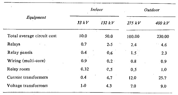
Table 1.2 shows the relative costs of the various equipment at different voltages.
Relay Cases and Circuit Modules:
Static relay circuit components are so small that a number of relay units formerly in separate cases can all be contained in a single case. Relay cases now tend to conform to internationally accepted standard rack dimensions (19 in or 482 mm width) and provide facilities for testing. Each rack can accommodate a large number of modules with standard being extracted before the main connector is removed, deenergizing them.
Table 1.2—Average Cost in Units per Circuit
The functional modular units are usually of 7 in or 177.8 mm height. Many manufacturers now make smaller plug in modules which can be plugged into a standard 19-in rack unit.
Thus, a one-relay module is defined by ASEA [Allmanna Svenska Elektriska Aktiebolaget] as equal to 41 x 85 mm2, a two-relay module as 83 X 85 mm2, a four-relay module as 83 x162 mm2 and an eight-relay module as 2 x(83 X 162 mm2).
The circuits are printed circuit types, the base being of a material which does not absorb moisture. Continuous improvement of components and the introduction of new components sometimes makes it difficult to implement a design in practice before newer and better techniques become available. Integrated circuits, for example, are available in large varieties and at cheaper prices, so that many manufacturers have already incorporated them in their relays. The reliability of Influence of Static Protective Relays in service has compared favourably with that of electromechanical relays and many times better than them.
Cost comparison between static and conventional relays has shown that at present there is a parity in cost and in same cases, especially in the case of the distance schemes, to be cheaper in static version. The price of a relay or a protection scheme does not depend entirely on the component and labour costs, but depends on other factors like developmental costs, prices of similar equipment from competitors, utility of the scheme, etc.
At present, most of the developmental work on static relays, has been carried out by the manufacturers although research papers do appear from others like academic institutions etc. The conversion of commercial manufacture and satisfactory type testing takes a very long time. In the case of Influence of Static Protective Relays, there is a need to merge both the experimental and developmental stages because of their considerable interdependence. There is a growing need for participation in this effort by the users and academic institutions in the development of new systems and in the exploitation of their advantages, This necessitates a continuous dialogue between relay manufacturers and such institutions who are involved in developmental activities.