Factors Affecting Transient Stability:
Factors Affecting Transient Stability – The two-machine system can be equivalently reduced to a single machine connected to infinite bus bar. The qualitative conclusions regarding system stability drawn from a two-machine or an equivalent one-machine infinite bus system can be easily extended to a multimachine system. In the last article we have studied the algorithm for determining the stability of a multimachine system.
It has been seen that some factors affecting transient Stability is greatly affected by the type and location of a fault, so that a power system analyst must at the very outset of a stability study decide on these two factors. In our examples we have selected a 3–phase fault which is generally more severe from point of view of power transfer. Given the type of fault and its location let us now consider other factors which affect transient stability and therefrom draw the conclusions, regarding methods of improving the transient stability limit of a system and making it as close to the steady state limit as possible.
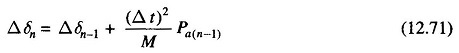
For the case of One machine connected to infinite bus, it is easily seen from Eq. (12.71) that an increase in the inertia constant M of the machine reduces the angle through which it swings in a given time interval offering thereby a method of improving stability but this cannot be employed in practice because of economic reasons and for the reason of slowing down the response of the speed governor loop (which can even become oscillatory) apart from an excessive rotor weight.
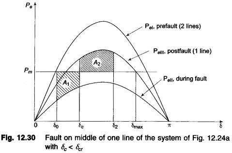
With reference to Fig. 12.30, it is easily seen that for a given clearing angle, the accelerating area decreases but the decelerating area increases as the maximum power limit of the various power angle curves is raised, thereby adding to the transient stability limit of the system. The maximum steady power of a system can be increased by raising the voltage profile of the system and by reducing the transfer reactance. These conclusions along with the various transient stability cases studied, suggest the following method of improving the transient stability limit of a power system.
- Increase of system voltages, use of AVR.
- Use of high speed excitation systems.
- Reduction in system transfer reactance.
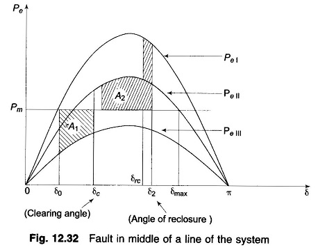
- Use of high speed reclosing breakers (see Fig. 12.32). Modern tendency is to employ single-pole operation of reclosing circuit breakers.
When a fault takes place on a system, the voltages at all buses are reduced. At generator terminals, these are sensed by the automatic voltage regulators which help restore generator terminal voltages by acting within the excitation system. Modern exciter systems having solid state controls quickly respond to bus voltage reduction and can achieve from one-half to one and one-half cycles (1/2-1 1/2 ) gain in critical clearing times for three-phase faults on the HT bus of the generator transformer.
![]()
Reducing transfer reactance is another important practical method of increasing stability limit Incidentally this also raises system voltage profile. The reactance of a transmission line can be decreased (i) by reducing the conductor spacing, and (ii) by increasing conductor diameter (see Eq. (2.37)). Usually, however, the conductor spacing is controlled by other features such as lightning protection and minimum clearance to prevent the arc from one phase moving to another phase. The conductor diameter can be increased by using material of low conductivity or by hollow cores. However, normally, the conductor configuration is fixed by economic considerations quite apart from stability. The use of bundled conductors is, of course, an effective means of reducing series reactance.
Compensation for line reactance by series capacitors is an effective and economical method of increasing stability limit specially for transmission distances of more than 350 km. The degree of series compensation, however, accentuates the problems of protective relaying, normal voltage profiles, and overvoltage’s during line-to-ground faults. Series compensation becomes more effective and economical if part of it is switched on so as to’ increase the degree of compensation upon the occurrence of a disturbance likely to cause instability. Switched series capacitors simultaneously decrease fluctuation of load voltages and raise the some factors affecting transient Stability limit to a value almost equal to the steady state limit. Switching shunt capacitors on or switching shunt reactors off also raises stability limits but the MVA rating of shunt capacitors required is three to six times the rating of switched series capacitors for the same increase in stability limit. Thus series capacitors are preferred unless shunt elements are required for other purposes, say, control of voltage profile.
Increasing the number of parallel lines between transmission points is quite often used to reduce transfer reactance. It adds at the same time to reliability of the transmission system. Additional line circuits are not likely to prove economical unit l after all feasible improvements have been carried out in the first two circuits.
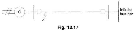
As the majority of faults are transient in nature, rapid switching and isolation of unhealthy lines followed by reclosing has been shown earlier to be a great help in improving the stability margins. The modern circuit breaker technology has now made it possible for line clearing to be done as fast as in two cycles. Further, a great majority of transient faults are line-to-ground in nature. It is natural that methods have been developed for selective single pole opening and reclosing which further aid the stability limits. With reference to Fig. 12.17, if a transient LG fault is assumed to occur on the generator bus, it is immediately seen that during the fault there will now be a definite amount of power transfer, as different from zero power transfer for the case of a three-phase fault. Also when the circuit breaker pole corresponding to the faulty line is opened, the other two lines (healthy ones) remain intact so that considerable power transfer continues to take place via these lines in comparison to the case of three-pole switching when the power transfer on fault clearing will be reduced to zero. It is, therefore, easy to see why the single pole switching and reclosing aids in stability problem and is widely adopted. Even when the stability margins are sufficient, single pole switching is adopted to prevent large swings and consequent voltage dips. Single pole switching and reclosing is, of course, expensive in terms of relaying and introduces the associated problems of over voltages caused by single pole opening owing to line capacitances. Methods are available to nullify these capacitive coupling effects.