How to Improve Voltage Stability in Power System:
How to Improve Voltage Stability in Power System – Voltage (load) stability, however, is now a main issue in planning and operating electric power systems and is a factor leading to limit power transfers. Voltage Stability in Power System is concerned with the ability of a power system to maintain acceptable voltages at all buses in the system under normal conditions and after being subjected to a disturbance. A Voltage Stability in Power System is said to have entered a state of voltage instability when a disturbance results in a progressive and uncontrollable decline in voltage.
Inadequate reactive power support from generators and transmission lines leads to voltage instability or voltage collapse, which have resulted in several major system failures in the world. They are:
- South Florida, USA, system disturbance of 17 May 1985, (transient, 4 sec)
- French system disturbances of December 19, 1978 and January 12, 1987, (longer term).
- Swedish system disturbance of December 27, 1983 (longer term, 55 sec)
- Japanese (Tokyo) system disturbance of July 23, 1987 (longer term, 20 min)
- NREB grid disturbance in India in 1984 and 1987.
- Belgium, Aug 4, 1982. (longer term, 4.5 min)
- Baltimore, Washington DC, USA, 5th July 1990 (longer term, insecure for hours)
Hence, a full understanding of how to improve voltage stability in power system phenomena and designing mitigation schemes to prevent voltage instability is of great value to utilities. Consequently over the last ten years, utility engineers, consultants and researchers have thoroughly studies voltage stability.
Voltage stability covers a wide range of phenomena. Because of this, voltage stability means different things to different engineers. Voltage instability and voltage collapse are used somewhat interchangeably by many researchers. Voltage instability or collapse is a faster dynamic process. As opposed to angle stability, the dynamics mainly involves the loads and the means for voltage control.
A power system at a given operating state is small-disturbance voltage stable if, following any small disturbance, voltages near loads are identical or close to the pre-disturbance values. The concept of small-disturbance voltage stability is related to steady-state stability (Chapter 12) and can be analyzed using small-signal (linearized) model of the system.
A Voltage Stability in Power System at a given operating state and subject to a given disturbance is voltage stable if voltages near loads approach post-disturbance equilibrium values. The concept of voltage stability is related to the transient stability of a power system. The analysis of voltage stability normally requires simulation of the system modelled by non-linear differential-algebraic equations.
A power system at a given operating state and subject to a given disturbance undergoes voltage collapse if post-disturbance equilibrium voltages are below acceptable limits. Voltage collapse may be total (blackout) or partial. The voltage instability and collapse may occur in a time frame of a second. In this case the term transient voltage stability is used. Sometimes it may take up to tens of minutes in which case the term long-term voltage stability is used.
The term voltage security means the ability of a system, not only to operate stably, but also to remain stable following any reasonably credible contingency or adverse system change such as load increases.
Voltage stability involves dynamics, but load flow based static analysis methods are generally used for quick and approximate analysis.
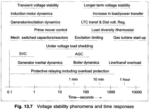
Figure 13.7 depicts how voltage stability can be classified into transient and long-term time frame.
Voltage stability problems normally occur in heavily stressed systems. Voltage stability and rotor angle (or synchronous) stability are more or less interlinked. Rotor angle stability, as well as voltage stability is affected by reactive power control. Voltage stability is concerned with load areas and load characteristics. For rotor angle stability, the main concern is the integration of remote power plants to a large system over long transmission lines. Voltage stability is basically load stability and rotor angle stability is basically generator stability. In a large inter-connected system, voltage collapse of a load area is possible without loss of synchronism of any generators.
The slower forms of voltage instability are often analysed as steady-state problems. ‘Snapshots’ in time following an outage or during load buildup are simulated. In addition to post-disturbance load flows, two other load flow based methods are widely used: P-V curves and Q-V curves. PV curves are used for conceptual analysis of voltage stability especially for radial systems.
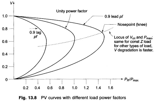
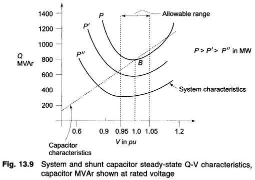
For carrying out static analysis, PV curves (Fig. 13.8), QV curves (Fig. 13.9), computation of nose point (see Fig. 13.8) and methods to quantify nose point i.e. proximity indicators are computed. Power flow analysis determines how Power System Voltage Stability equilibrium point values such as voltages and line flows vary as various system parameters and controls are changed. Two values of load voltage exist for each value of load. The upper one indicates stable voltage whereas lower one is the unacceptable value (multiple load flow). At limiting stage of voltage stability i.e. at nose point single load flow solution exists. Nearer the nose point, lesser is the stability margin.
PV Curve Voltage Stability:
- Generator terminal voltage should be raised.
- Generator transformer tap value may be increased.
- Q-injection should be carried out at an appropriate location.
- Load-end OLTC (on-load tap changer) should be suitably used.
- For under voltage conditions, strategic load shedding should be resorted
System reinforcement may be carried out by installing new transmission lines between generation and load centers. Series and shunt compensation may be carried out and SVCs (static var compensation) may be installed. Generation rescheduling and starting-up of gas turbines may be carried out.
Practical aspects of Q-flow problems leading to voltage collapse in EHV lines:
- For long lines with uncontrolled buses, receiving-end or load voltages increase for light load conditions and decrease for heavy load conditions.
- For radial transmission lines, if any loss of a line takes place, reactance goes up, I2X loss increases resulting in increase in voltage drop. This should be suitably compensated by local Q injection. Of course this involves cost. If there is a shortage of local Q source, then import of Q through long line may have to be resorted to. However, this is not desirable.
Only the operating points above the critical points represent satisfactory operating conditions. At the ‘knee’ of the V-P curve, the voltage drops rapidly with an increase in load demand. Power-flow solution fails to converge beyond this limit indicating instability. Operation at or near the stability limit is impractical and a satisfactory operating condition is ensured by permitting sufficient “power margin”.
Voltage Collapse:
Voltage collapse is the process by which the sequence of events accompanying voltage instability leads to unacceptable voltage profile in a significant part of the Voltage Stability in Power System. It may be manifested in several different ways. Voltage collapse may be characterized as follows:
- The initiating event may be due to variety of reasons: Small gradual system changes such as natural increase in system load, or large sudden disturbances such as loss of a generating unit or a heavily loaded line.
- The crux of the problem is the inability of the system to meet its reactive When transport of reactive power from neighboring areas is difficult, any change that requires additional reactive power support may eventually lead to voltage collapse.
- The voltage collapse generally manifests itself as a slow decay of voltage. It is the result of an accumulative process involving the actions and interactions of many devices, controls, and protective systems. The time frame of collapse in such cases would be of the order of several minutes. Voltage collapse is strongly influenced by system conditions and
- Reactive compensation can be made most effective by the judicious choice of a mixture of shunt capacitors, static var system and possibly synchronous condensers.
- Reactive compensation can be made most effective by the judicious choice of a mixture of shunt capacitors, static var system and possibly synchronous condensers.
Methods of How to Improve Voltage Stability in Power System:
Voltage stability can be improved by adopting the following means:
- Enhancing the localised reactive power support (SVC) is more effective and C-banks are more economical. FACTS devices or synchronous condenser may also be used.
- Compensating the line length reduces net reactance and power flow
- Additional transmission line may be erected. It also improves reliability.
- Enhancing excitation of generator, system voltage improves and Q is supplied to the system.
- HVDC tie may be used between regional grids.
- By resorting to strategic load shedding, voltage goes up as the reactive burden is reduced.
Future Trends and Challenges:
- Optimal siting of FACTs devices.
- Better and probabilistic load modelling.
- Develop techniques and models for study of non-linear dynamics of large size systems. For example, new methods to obtain network equivalents suitable for voltage stability analysis.