Automation in Digital Instruments:
Automation in Digital Instruments – One of the advantages of digital multimeters is their ease of operation. The reading is easy to take and does not lend itself to errors of interpretation. Moreover, the number of ranges is limited because the ranges move in steps of 10 (instead of the √10 steps used for analog instruments). Demand from users for simple forms of computation signaling and control, and advances in digital circuitry have led to further development, in which more and more automatic functions have been incorporated in digital voltmeters. Nearly all instruments today have automatic polarity display and automatic decimal point positioning, while many have automatic ranging and zeroing too.
This Automation in Digital Instruments includes automatic polarity indication, automatic ranging, and automatic zeroing.
1. Automatic Polarity Indication:
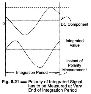
The polarity indication is generally obtained from the information in the ADC. For integrating ADCs, only the polarity of the integrated signal is of importance. The polarity should thus be measured at the very end of the integration period (see Fig. 6.21). As the length of the integration period is determined by counting a number of clock pulses, it is logical to use the last count or some of the last counts to start the polarity measurement. The output of the integrator is then used to set the polarity flip-flop, the output of which is stored in memory until the next measurement is made.
2. Automatic Ranging:
The object of automatic ranging is to get a reading with optimum resolution under all circumstances (e.g. 170 mV should be displayed as 170.0 and not as 0.170). Let us take the example of a 3½ digit display, i.e. one with a maximum reading of 1999. This maximum means that any higher value must be reduced by a factor of 10 before it can be displayed (e.g. 201 mV as 0201). On the other hand, any value below 0200 can be displayed with one decade more resolution (e.g. 195 mV as 195.0). In other words, if the display does not reach a value of 0200, the instrument should automatically be switched to a more sensitive range, and if a value of higher than 1999 is offered, the next less sensitive range must be selected.
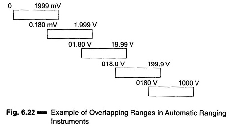
Generally the lower limit is taken lower than 0200 (example 0180). Otherwise, a voltage exhibiting slight fluctuations around 2000 would be displayed successively as 1999.9, 0200 and 0201, which would be confusing. By introducing an overlap in the ranges (see Fig. 6.22), we ensure that all values are displayed in the same range (in the above example, as 0199, 0200 or 0201). Values around 0180 also give a stable display e.g. 1798, 1800 and 1807).
The design of an automatic ranging system is indicated in the block diagram in Fig. 6.23.
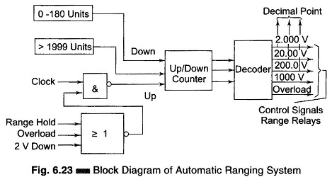
The information contained in the counter of the ADC yields a control pulse for down ranging when the count is less than 180 and one for up ranging when the count exceeds 1999 units. The Up/Down counter of the automatic ranging circuit reacts to this information at the moment that a clock pulse (a pulse at the end of the measuring period, also used to transfer new data to memory), is applied, and the new information is used to set the range relays via the decoder. At the same time the decimal point in the display is adapted to the new range, when more than range step has to be made, several measuring periods are needed to reach the final result. Clock pulses, and so automatic ranging, can be inhibited, for example, by a manual range hold command, by a signal that exceeds the maximum range (only for up counts), and course by reaching the most sensitive range, but then only for down counts.
3. Automatic Zeroing:
Each user of a voltmeter expects the instrument to indicate zero when the input is short-circuited. In a digital voltmeter with a maximum reading of 1999, a zero error of 0.05% of full scale deflection is sufficient to give a reading of 0001. For this reason, and in the interests of optimum accuracy with low valued readings, a zero adjustment is necessary. To increase the ease of operation, many instruments now contain an automatic zeroing circuit.
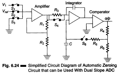
In a system used in several multimeters, the zero error is measured just before the real measurement and stored as an analog signal. A simplified circuit diagram of a circuit that can be used for this purpose is given in Fig. 6.24, for a dual slope ADC.
Before the real measurement is made, switches S3, S4 and S5 are closed, say for 50 ms, thus grounding the input, giving the integrator a short RC time, and connecting the output of the comparator to capacitor C. This capacitor is now charged by the offset voltages to the amplifier, the integrator and the comparator. When switches S3, S4 and S5 are opened again to start the real measurement, the total offset voltage of the circuit (equal to zero error) is stored in this capacitor, and the real input voltage is measured correctly.