Beat Frequency Oscillator (BFO) | Block Diagram | Working and Limitations:
In this Beat Frequency Oscillator, the outputs of two RF oscillators are applied to a square law detector and the resulting difference frequency is amplified. The main advantage of this type of oscillator is that a stable continuous output covering the entire AF range can be realized by simple variation of the tuning capacitor in one of the oscillators.
Beat Frequency Oscillator Block Diagram:
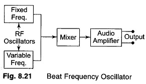
In the circuit given in Fig. 8.21, the voltages obtained from two RF oscillators operating at slightly different frequencies are combined and applied to a mixer circuit. The difference frequency current that is thus produced represents the desired oscillations. The practical value of a Beat Frequency Oscillator arises from the fact that a small or moderate percentage variation in the frequency of one of the individual oscillators (such as can be obtained by the rotation of the shaft controlling a variable tuning capacitor) varies the beat or difference output continuously from a few c/s to throughout the entire AF or video frequency range. At the same time, the amplitude of the difference frequency output is largely constant as frequency is varied.
The principal factors involved in the performance of a Beat Frequency Oscillator are the frequency stability of individual oscillators, the tendency of the oscillators to synchronize at very low difference frequencies, the wave shape of the difference frequency output, and the tendency for spurious beat notes to be produced.
Frequency stability of the individual oscillators is important, because a slight change in their relative frequency would cause a relatively large change in the difference frequency. To minimize the drift of the difference frequency with time, the individual oscillators should have high inherent frequency stability with respect to changes in temperature and to supply voltage variations, and they should be as alike electrically, mechanically and thermally, as possible.
In this way, frequency changes are minimized and the frequency changes that do take place tend to be the same in each of the individual oscillators and so have little effect on the difference in their frequencies.
The two RF oscillators must be completely isolated from each other. If coupling of any type exists between them, they will synchronize when the difference is small. Hence, low values of difference frequency are impossible to obtain, and in addition cause interaction between the oscillators that results in a highly distorted wave shape.
(To ensure low distortion, one of the voltages applied to the mixer, preferably the one derived from the fixed frequency oscillator, should be considerably smaller than the voltage derived from the other oscillator, and preferably free of harmonics.)
Beat Frequency Oscillator are commonly affected with spurious beat notes, sometimes called whistles. These effects are usually the result of cross-modulation in the AF amplifier between high order RF harmonics generated by the mixer. These spurious whistles often appear when the output frequency is high.
Whistles can be eliminated by operating the mixer so as to minimize the production of RF harmonics, and by using a filter and shielding to prevent the harmonics that are generated in the mixer from reaching the amplifier circuit.
