Integrating Type DVM (Voltage to Frequency Conversion):
The principle of operation of an Integrating Type DVM is illustrated in Fig. 5.5.
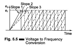
A constant input voltage is integrated and the slope of the output ramp is proportional to the input voltage. When the output reaches a certain value, it is discharged to 0 and another cycle begins. The frequency of the output waveform is proportional to the input voltage. The block diagram is illustrated in Fig. 5.6.
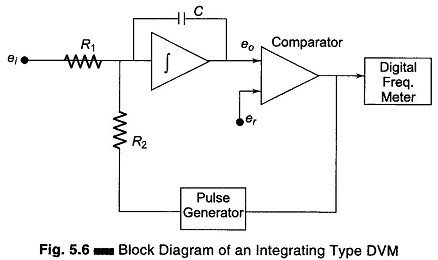
The input voltage produces a charging current, ei/R1 that charges the capacitor ‘C’ to the reference voltage er. When er is reached, the comparator changes state, so as to trigger the precision pulse generator. The pulse generator produces a pulse of precision charge content that rapidly discharges the capacitor. The rate of charging and discharging produces a signal frequency that is directly proportional to ei.
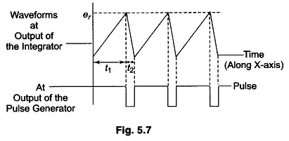
The voltage-frequency conversion can be considered to be a dual slope method, as shown in Fig. 5.7.
Referring to Eq. 5.3 we have

But in this case er and t2 are constants.
Let
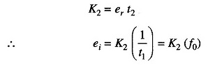
The output frequency is proportional to the input voltage ei. This DVM has the disadvantage that it requires excellent characteristics in linearity of the ramp. The ac noise and supply noise are averaged out.