Synchronous Generator Ratings and Loss Dissipation:
The Synchronous Generator Ratings and Loss Dissipation is its operating voltage, frequency, speed and kVA/MVA output at a specified power factor. In case of motors the output rating is given in kW (older practice was to specify the rated output in horse-power (1 hp = 746 W)). The dc machines are rated in terms of voltage and power output in kW. The frequency specification of ac machines is normally the standard supply frequency, i.e. 50 Hz—it is 60 Hz on the American continent. The rated voltage is specified as a standard value, viz 230 V/ 400 V/3.3 kV/6.6 kV/11 kV. Most manufacturers build small and medium sized motors in standard kW sizes.
Insulation which is used in intricate forms is the most vulnerable part of a machine being highly susceptible to temperature which is the major factor in determining its lifetime and therefore that of the machine. As a rule of thumb the lifetime of a machine is reduced to one-half for every 8-10 °C rise in temperature. Acceptable life expectancy of electric power equipment being 10-30 years, the highest temperature of insulation anywhere in the machine has to be limited to a value depending upon the class of insulation employed. The maximum output that a machine can supply without exceeding a specified temperature rise above the ambient (40 °C as per ISI), is known as the continuous rating of the machine. The continuous Synchronous Generator Ratings and Loss Dissipation as determined by temperature rise, limits the machine losses generally assuring an acceptable value of machine efficiency. Any other specific performance figure(s) (say the breakdown torque of induction motor) must be independently met by the machine designer.
Both iron and copper being the seats of losses in a machine, the temperature distribution in the machine is quite complex. This problem is greatly simplified by assigning a single temperature to define the thermal state of the machine. The single temperature is determined by the rise in resistance of windings as measured from the machine terminals. In super-size synchronous generators, thermocouples are embedded during manufacture to track temperature of hot-spots predetermined by the designer through heat transfer studies.
ISI specifications classify insulation for industrial machines as Class B, Class F and Class H. Class B insulation includes mica, glass fibre, asbestos, and other similar materials with suitable binding substances. The highest temperature rise (40 °C above ambient) allowed for this class of insulation is 130 °C. Class F insulation also includes mica, glass fibre, and synthetic substances, but it must be able to withstand a higher temperature of 155 °C. Class H can withstand a still higher temperature of 180 °C and may consist of materials like silicone elastomer and combinations in various forms of mica, glass fibre, asbestos, etc. with silicone resins for bonding.
A continuous-rated motor must operate successfully ±10% variation of the rated voltage and ±5% variation of the rated frequency. The combined variation of voltage and frequency in a direction to adversely affect losses (V increases, f reduces) must not exceed 10%. It is further expected that the continuous-rated motors are built with ample safety margin so as be capable of withstanding short-time overloads of 25% with 10% reduction in voltage without excessive temperature rise.
In industrial applications certain situations require the motor to be loaded for short time periods followed by long cooling intervals. Such motors are short-time rated for standard periods of 5, 15, 20, 30 and 60 min. These motors are specially designed with higher flux densities in iron and higher current densities in copper. As a result they have better torque producing capability but lower thermal capacity when compared to continuous-rated motors.
Short-time rating of a continuous-rated motor is much more than its continuous rating because of the heat storage in thermal capacity of the machine during the heat transient under short-time loading. This is illustrated in Fig. 5.52. The thermal transient has an exponential growth (a single time constant) with a steady temperature rise of (PLRT) where PL represents the motor loss in heat units at a particular load and RT is the overall thermal resistance of the cooling system. It is evident from Fig. 5.52
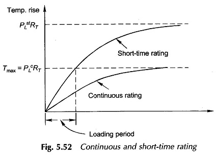
that PstL (short-time loading loss) allowed for a specified loading period is more than PcL(continued loading loss) without the machine exceeding the allowable temperature rise. Hence as the loading period is reduced, the motor short-time rating increases.
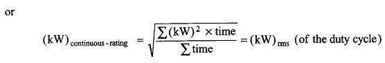
In industrial applications of motors a typical problem is the determination of the size of a continuous-rated motor for a given duty cycle—the duty cycle of a “planer” may be visualized as a simple example; during the forward stroke the motor is on full-load while it is practically unloaded during the return stroke. A crude yet reliable method of motor selection is to assume that the motor losses are proportional to the square of loading (this overemphasizes I2R loss as compared to the constant core-loss). The average loss during a duty cycle is proportional to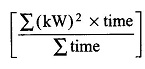
where kW = motor loading in a period of duty cycle. The continuous-rated motor which has the same loss is given by
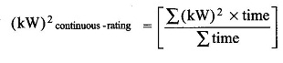
If stand-still period(s) are involved as part of the duty cycle (as in a crane) the above relationship must be modified as under
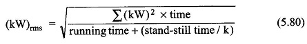
where the constant (k > 1) accounts for poor ventilation (cooling) during the standstill period(s) where there is no forced cooling. For open-type motors, k = 4. It is tacitly assumed in Eq. (5.80) that the duty cycle period is sufficiently less than the time for the motor to reach almost its steady temperature rise when continuously loaded to its continuous-rating.
The errors involved in the (kW)rms-method are swamped out when the nearest higher standard rating, e.g. 90 kW motor is selected for (kW)rms = 85.
A duty cycle requiring high torque peaks cannot be satisfied by (kW)rms choice which has a thermal basis. Short-time rated motors as already mentioned are better suited for such applications because of their better torque-producing capabilities.
Loss Dissipation (Cooling):
To prolong insulation life-time to an acceptable value, the heat generated owing to loss in a machine must be dissipated fast enough so that the temperature rise does not exceed the allowable limit for a specified ambient temperature. In fact it is the improvement in heat transfer technology that has helped in a major reduction in machine sizes for given Synchronous Generator Ratings and Loss Dissipation, in particular for large-size machines.
Combined conduction and forced convective cooling are the practical means of removing heat of losses from all electric machinery. Because of limited allowable temperature rise, radiation does not make any significant contribution to loss dissipation.
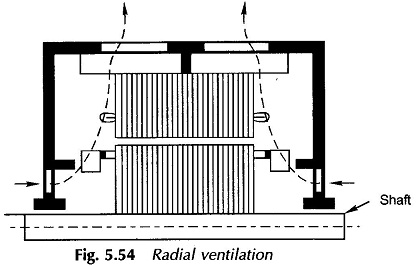
Radial ventilation:
Radial ventilation is commonly employed wherein the natural centrifugal action of the rotor may be supplemented by the rotor fan. Figure 5.54 shows the radial ventilation scheme suitable for machines up to 20 kW.
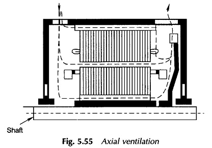
Axial ventilation:
Axial ventilation scheme of Fig. 5.55 is suitable for machines of moderate outputs and high speeds.
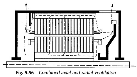
Combined radial and axial ventilation:
Totally–enclosed:
Totally enclosed machine presents a special ventilation problem as the inside of the machine has no air-connection with outside. In such machines heat is transferred to the enclosure (called carcass) by an internal fan and from where it is removed to the ambient by an external fan mounted on the shaft. The cooling in a totally enclosed machine cannot be as efficient as in an open-type machine.
Losses being roughly proportional to the volume of material increase as the cube of the linear dimensions, while the cooling surface increases as the square of the same. Therefore, the loss dissipation problem becomes more intense in large turbogenerators.
For large machines, which may require several tonnes of cooling air/hour, forced ventilation is used wherein air is passed through a cleaning filter before being forced into the machine, for cooling purposes. A more compact scheme of securing clean cooling air is the closed-circuit system as employed for turbo-generators of small Synchronous Generator Ratings and Loss Dissipation. In this system hot air is cooled by a water-cooled heat exchanger.
Hydrogen Cooling:
For large turbo-generators, hydrogen is commonly used as a cooling medium in a closed circuit. The following properties of hydrogen make it most suited for this purpose.
- Hydrogen has a density of 1/14 of that of air at the same temperature and pressure, reducing thereby windage losses and noise.
- On an equal weight basis, the specific heat of hydrogen is 14 times that of air. Therefore, for the same temperature and pressure, the heat-storing capacity/ unit volume of hydrogen is the same as that of air.
- The heat-transfer capability of hydrogen by forced convection over a hot surface is 1.5 times that of air.
- The thermal conductivity of hydrogen is seven times that of air.
- By use of hydrogen environment, the life of insulation is prolonged and the maintenance cost goes down because of the absence of dirt, moisture and
- The hydrogen-air mixture does not explode so long as air content is less than 30%.
To avoid air leaking into the hydrogen circuit, hydrogen pressure is maintained above 1 atm. Hydrogen cooling at 1, 2 and 3 atm can raise the Synchronous Generator Ratings and Loss Dissipation of a machine by 15%, 30% and 40% respectively. Hydrogen cooling reduces the temperature and resistance of windings and hence the losses to be dissipated. This fact marginally raises the full-load efficiency of the machine (by about 0.5%).
The machine and its water-cooled heat exchanger for cooling hydrogen are enclosed in a gas-tight envelope; the most intricate problem being that of sealing the bearings. Oil-filled gas-seals are used for this purpose. Further, the envelope must be explosion-proof.
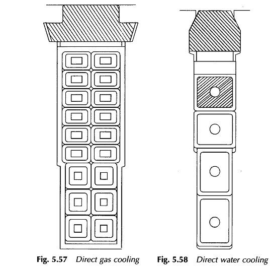
Direct Gas cooling:
For a machine of 100 MW or more, the temperature gradient over the conductor insulation is high enough to call for direct contact between the coolant and conductor. For this purpose, the rotor conductor comprises hollow tubes as shown in Fig. 5.57 through which hydrogen is circulated by means of flexible connections.
Direct Water Cooling:
Turbo-generators of the highest rating have a hydrogen-cooled stator core and a direct water-cooled stator and rotor windings. The speed of circulating water must be limited to 2.5 m/s to avoid erosion and cavitation. Figure 5.58 shows the arrangement for direct water-cooling of the rotor winding which is most desirable because of high electric loading of rotor and is mechanically most difficult. Direct water-cooling of the stator winding requires flexible water-tube connections with insulation against high voltages and low water conductivity.