Single Phase Synchronous Generator:
Certain applications, usually restricted to less than 10 kVA are better served by a Single Phase Synchronous Generator. Examples are emergency, domestic/office supply, portable power for construction tools etc. Because of simplicity of distribution wiring, these loads are better served by a single-phase arrangement. Single Phase Synchronous Generator stator winding can be arranged in two ways.
- A 12-lead three-phase winding connected to operate single-phase.
- Specialized single-phase wound stator.
In the first arrangement several connections are possible but all have to be derated compared to normal three-phase connection. Two connections are indicated in Fig. 8.74 and are compared to three-phase series star in terms of voltage and pu kVA rating.
In a Single Phase Synchronous Generator, while rotor is similar to that of a three-phase, stator is wound single phase with short-pitched coils (short pitch γ(= SPP) slots). Thus one third of stator slots are left unwound and winding has to be single layer. Obviously

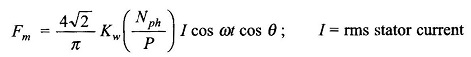
the rating of the machine is 2/3rd that of three-phase wound generator. While the rotor has salient poles and produces a field distributed sinusoidally in space (because of shaping of pole faces), the stator which is single phase produces an oscillating field along a fixed axis. The expression for the fundamental component of stator field is as given in Eq. (5.36).
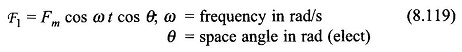
where
Equation (8.119) can be trigonometrically split as
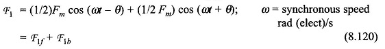
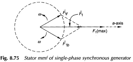
when F1f is a sinusoidally distributed field rotating in positive direction of θ (forward rotating) and F1b is a backward rotating field. Both these fields rotate at synchronous speed as shown in Fig. 8.75 where fields are represented as rotating vectors F̅1f and F̅1b, while the resultant field is an oscillating vector F̅1 field in space.
The forward rotating stator field locks into the rotor field and both move together producing electromagnetic torque and causing conversion of energy from mechanical to electrical. Figure 8.76(a) shows the rotor and stator fields at the instant I1 (max). The corresponding phasor diagram is drawn in Fig. 8.76(b) wherein only those phasors which are stationary w.r.t. each are indicated. Assuming Xq to be small, the terminal voltage can be related to excitation emf Ee (suffix e is used to avoid confusion that would be caused by suffix f used so far) by Xd as obtained by OC and SC test. The effects caused by F̅1b which rotates at ω w.r.t. stator and at speed 2ω w.r.t. to rotor in opposite direction is discussed below.
Backward rotating field F1b induces second harmonic current in the field winding (and also damper winding) and fundamental frequency voltage in stator winding. The second harmonic current in the field winding causes an oscillating field along the d-axis at the same frequency. By the argument presented earlier this field can be split into two rotating fields rotating at ± 2ω w.r.t. rotor or 3ω and – ω w.r.t. stator. Thus the stator winding has induced in it third harmonic and fundamental frequency voltages. The fundamental frequency voltages induced in stator due to F̅1f and F̅1b are both accounted for in Xd. The third harmonic voltages induced in stator cause third harmonic current in the line. Unlike slot harmonics these cannot be eliminated (or attenuated) by chording. But their amplitude is reduced by self-inductance of the field winding, eddy currents in rotor and second harmonic currents in the damper bars.