Tunnel Diode Parallel Amplifier Circuit:
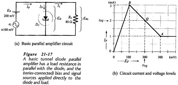
For operation as an amplifier, a tunnel diode must be biased to the center of its negative resistance region. Figure 21-17(a) shows the basic circuit of a Tunnel Diode Parallel Amplifier Circuit.
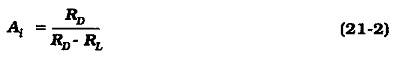
Load resistor RL is connected in parallel with diode D1 and supplied with current from voltage source EB and signal source es. Figure 21-17(b) uses the tunnel diode piecewise linear characteristics to show the dc conditions of the diode when the signal voltage is zero (es = 0), and when es = ±100 mV.
The current gain equation for a Tunnel Diode Parallel Amplifier Circuit can be shown to be,
Note that RD is already taken as negative in Eq. 21-2, so that only the absolute value should be used in calculating Ai. For RD = 100 Ω and RL = 80Ω,![]()
From Eq. 21-2, it is seen that (when RL ≪ RD, Ai ≈ 1), (when RL ≫ RD, Ai < 1), and (when RL = RD, Ai = ∞). A current gain of infinity means that the circuit is likely to oscillate. For maximum stable current gain, RL should be selected just slightly less than RD.
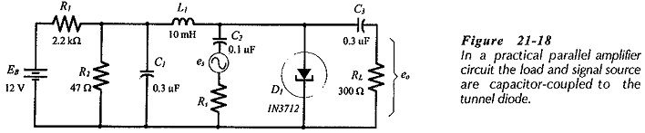
Figure 21-18 shows the circuit of a practical tunnel diode parallel amplifier. The signal voltage es and load resistor RL are capacitor-coupled to the diode, while dc bias is provided by source voltage EB and voltage divider R1 and R2. Inductor L1 and capacitor C1 isolate the bias supply from ac signals.
A tunnel diode series amplifier can be constructed. In this case the device is connected in series with the load, and voltage amplification is obtained instead of current amplification. Oscillators and switching circuits can also be constructed using tunnel diodes.