DC Distribution Calculation:
In addition to the methods of feeding discussed above, a DC Distribution Calculation may have
- concentrated loading
- uniform loading
- both concentrated and uniform loading.
The concentrated loads are those which act on particular points of the distributor. A common example of such loads is that tapped off for domestic use. On the other hand, distributed loads are those which act uniformly on all points of the distributor. Ideally, there are no distributed loads. However, a nearest example of distributed load is a large number of loads of same wattage connected to the DC Distribution Calculation at equal distances.
In DC Distribution Calculation, one important point of interest is the determination of point of minimum potential on the distributor. The point where it occurs depends upon the loading conditions and the method of feeding the distributor. The distributor is so designed that the minimum potential on it is not less than 6% of rated voltage at the consumer’s terminals. In the next sections, we shall discuss some important cases of d.c. distributors separately.
DC Distributor Fed at one End—Concentrated Loading:
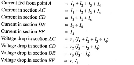
Fig. 13.5 shows the single line diagram of a 2-wire d.c. distributor AB fed at one end A and having concentrated loads I1, 12, 13 and 14 tapped off at points C, D, E and F respectively.
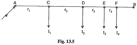
Let r1, r2, r3 and r4 be the resistances of both wires (go and return) of the sections AC, CD, DE and EF of the distributor respectively.
Total voltage drop in the DC Distribution Calculation is
![]()
It is easy to see that the minimum potential will occur at point F which is farthest from the feeding point A.
Uniformly Loaded Distributor Fed at One End
Fig 13.11 shows the single line diagram of a 2-wire d.c. distributor AB fed at one end A and loaded uniformly with i amperes per metre length. It means that at every 1 m length of the distributor, the load tapped is i amperes. Let l metres be the length of the distributor and r ohm be the resistance per metre run.
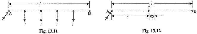
Consider a point C on the distributor at a distance x metres from the feeding point A as shown in Fig. 13.12. Then current at point C is
![]()
Now, consider a small length dx near point C. Its resistance is r dx and the voltage drop over length dx is
![]()
Total voltage drop in the distributor upto point C is
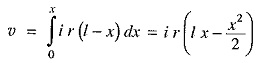
The voltage drop upto point B (i.e. over the whole distributor) can be obtained by putting x = l in the above expression.
Voltage drop over the distributor AB
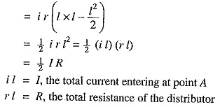
Thus, in a uniformly loaded distributor fed at one end, the total voltage drop is equal to that produced by the whole of the load assumed to be concentrated at the middle point.
Distributor Fed at Both Ends — Concentrated Loading:
Whenever possible, it is desirable that a long distributor should be fed at both ends instead of at one end only, since total voltage drop can be considerably reduced without increasing the cross-section of the conductor. The two ends of the distributor may be supplied with (i) equal voltages (ii) unequal voltages.
1.Two ends fed with equal voltages: Consider a distributor AB fed at both ends with equal voltages V volts and having concentrated loads I1, I2, I3, I4 and I5 at points C, D, E, F and G respectively as shown in Fig. 13.14. As we move away from one of the feeding points, say A, p.d. goes on decreasing till it reaches the minimum value at some load point, say E, and then again starts rising and becomes V volts as we reach the other feeding point B.
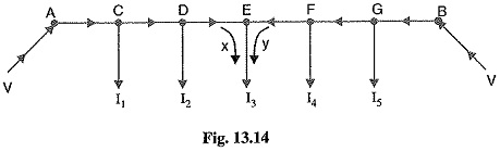
All the currents tapped off between points A and E (minimum p.d. point) will be supplied from the feeding point A while those tapped off between B and E will be supplied from the feeding point B. The current tapped off at point E itself will be partly supplied from A and partly from B. If these currents are x and y respectively, then,
![]()
Therefore, we arrive at a very important conclusion that at the point of minimum potential, current comes from both ends of the DC Distribution Calculation.
Point of minimum potential. It is generally desired to locate the point of minimum potential. There is a simple method for it. Consider a distributor AB having three concentrated loads I1, I2 and I3 at points C, D and E respectively. Suppose that current supplied by feeding end A is IA. Then current distribution in the various sections of the distributor can be worked out as shown in Fig. 13.15 (i). Thus
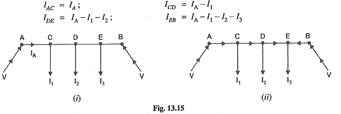

From this equation, the unknown IA can be calculated as the values of other quantities are generally given. Suppose actual directions of currents in the various sections of the distributor are indicated as shown in Fig. 13.15 (ii). The load point where the currents are coming from both sides of the distributor is the point of minimum potential i.e. point E in this case
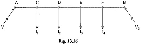
(ii) Two ends fed with unequal voltages. Fig. 13.16 shows the distributor AB fed with unequal voltages ; end A being fed at V1 volts and end B at V2 volts. The point of minimum potential can be found by following the same procedure as discussed above. Thus in this case,
![]()
Uniformly Loaded Distributor Fed at Both Ends:
We shall now determine the voltage drop in a uniformly loaded distributor fed at both ends. There can be two cases viz the distributor fed at both ends with (i) equal voltages (ii) unequal voltages.
The two cases shall be discussed separately.
(i) Distributor fed at both ends with equal voltages. Consider a distributor AB of length l metres, having resistance r ohms per metre run and with uniform loading of i amperes per metre run as shown in Fig. 13.24. Let the DC Distribution Calculation be fed at the feeding points A and B at equal voltages, say V volts. The total current supplied to the distributor is i l. As the two end voltages are equal, therefore, current supplied from each feeding point is i l/2 i.e.
Current supplied from each feeding point
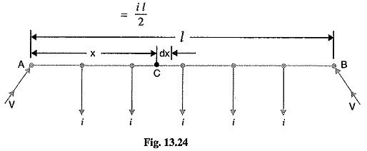
Consider a point C at a distance x metres from the feeding point A. Then current at point C is
![]()
Now, consider a small length dx near point C. Its resistance is r dx and the voltage drop over length dx is
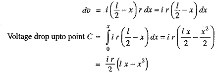
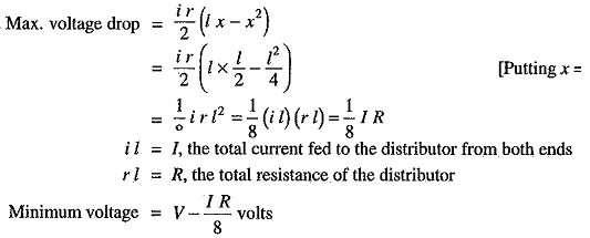
Obviously, the point of minimum potential will be the mid-point. Therefore, maximum voltage drop will occur at mid-point i.e. where x =l/2.
(ii) Distributor fed at both ends with unequal voltages. Consider a distributor AB of length (metres having resistance r ohms per metre run and with a uniform loading of i amperes per metre run as shown in Fig. 13.25. Let the DC Distribution Calculation be fed from feeding points A and B at voltages VA and VB respectively.
Suppose that the point of minimum potential C is situated at a distance x metres from the feedingvpoint A. Then current supplied by the feeding point A will be i x.
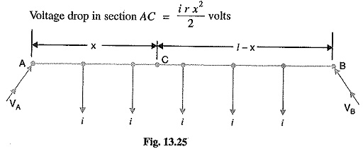
As the distance of C from feeding point B is (1— x), therefore, current fed from B is i (l – x).
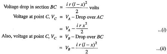
From equations (i) and (ii), we get,
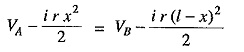
Solving the equation for x, we get,
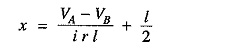
As all the quantities on the right hand side of the equation are known, therefore, the point on the distributor where minimum potential occurs can be calculated.
Distributor with Both Concentrated and Uniform Loading:
There are several problems where a distributor has both concentrated and uniform loadings. In such situations, the total drop over any section of the distributor is equal to the sum of drops due to concentrated and uniform loading in that section.