Three Wire DC Distribution System:
The great disadvantage of direct current for general power purposes lies in the fact that its voltage cannot readily be changed, except by the use of rotating machinery, which in most cases is too expensive. The problem can be solved to a limited extent by the use of Three Wire DC Distribution System which makes available two voltages viz. V volts between any outer and neutral and 2V volts between the outers. Motor loads requiring high voltage are connected between the outers whereas lighting and heating loads requiring less voltage are connected between any one outer and the neutral. Due to the availability of two voltages, Three Wire DC Distribution System is preferred over 2-wire system for d.c. distribution.
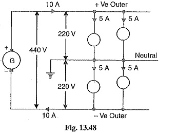
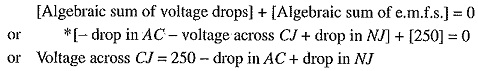
Fig. 13.48 shows the general principles of a Three Wire DC Distribution System. It consists of two outers and a middle or neutral wire which is earthed at the generator end. The potential of the neutral wire is half-way between the potentials of the outers. Thus, if p.d. between the outers is 440 V, then positive outer is at 220 V above the neutral and negative outer is 220 V below the neutral. The current in the neutral wire will,depend upon the loads applied to the two sides.
- If the loads applied on both sides of the neutral are equal (i.e. balanced) as shown in Fig 48, the current in the neutral wire will be zero. Under these conditions, the potential of the neutral will be exactly half-way between the potential difference of the outers.
- If the load on the positive outer (I1) is greater than on the negative outer (I2), then out of balance current I1 — I2 will flow in the neutral wire from load end to supply end as shown in Fig. 13.49 (i). Under this condition, the potential of neutral wire will no longer be midway between the potentials of the outers.
- If the load on the negative outer (I2) is greater than on the positive outer (I1), then out of balance current I2 — I1 will flow in the neutral from supply end to load end as shown in Fig. 13.49 (ii). Again, the neutral potential will not remain half-way between that of the outers.
- As the neutral carries only the out of balance current which is generally small, therefore, area of X-section of neutral is taken half as compared to either of the outers.
It may be noted that it is desirable that voltage between any outer and the neutral should have the same value. This is achieved by distributing the loads equally on both sides of the neutral.
Current Distribution in Three Wire DC System:
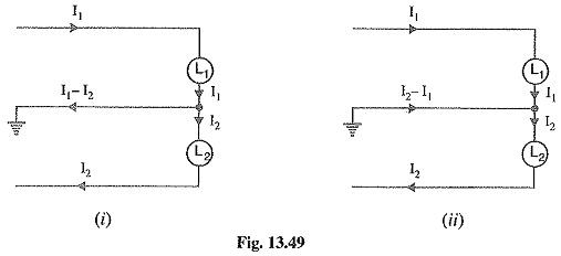
Fig. 13.50 shows a 3-wire 500/250 V d.c. distributor. Typical values of loads have been assumed to make the treatment more illustrative. The motor requiring 500 V is connected across the outers and takes a current of 75 A. Other loads requiring lower voltage of 250 V are connected on both sides of the neutral.
Applying Kirchhoff ‘s current law, it is clear that a current of 120 A enters the positive outer while 130 A comes out of the negative outer. Therefore, 130 — 120 = 10 A must flow in the neutral at point N. Once the magnitude and direction of current in the section NJ is known, the directions and magnitudes of currents in the other sections of the neutral can be easily determined. For instance, the currents meeting at point K must add up to 40 A to supply the load KH. As seen in Fig. 13.50, 20A of CJ and 10A of NJ flow towards K, the remaining 10A coming from point L. The current of 25A of load DL is divided into two parts ; 10A flowing along section LK and the remaining 15 A along the section LO to supply the load OG.
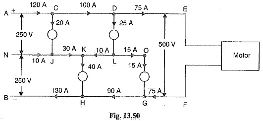
Load-point voltages: Knowing the currents in the various sections of the outers and neutral, the voltage at any load point can be determined provided resistances are known. As an illustration, let us calculate the voltage across load CJ of Fig.13.50. Applying Kirchhoff’s voltage law to the loop ACJNA, we have,