DC Distribution System:
It is a common knowledge that electric power is almost exclusively generated, transmitted and distributed as a.c. However, for certain applications, d.c. supply is absolutely necessary. For instance, d.c. supply is required for the operation of variable speed machinery (i.e., d.c. motors), for electrochemical work and for congested areas where storage battery reserves are necessary. For this purpose, a.c. power is converted into d.c. power at the substation by using converting machinery e.g., mercury arc rectifiers, rotary converters and motor-generator sets. The DC Distribution System from the substation may be obtained in the form of
- Two Wire DC Distribution System
- Three Wire DC Distribution System
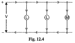
(i) Two Wire DC Distribution System: As the name implies, this system of distribution consists of two wires. One is the outgoing or positive wire and the other is the return or negative wire. The loads such as lamps, motors etc. are connected in parallel between the two wires as shown in Fig. 12.4. This system is never used for transmission purposes due to low efficiency but may be employed for distribution of d.c. power.
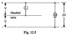
(ii) Three Wire DC Distribution System: It consists of two outers and a middle or neutral wire which is earthed at the substation. The voltage between the outers is twice the voltage between either outer and neutral wire as shown in Fig. 12.5. The principal advantage of this system is that it makes available two voltages at the consumer terminals viz., V between any outer and the neutral and 2V between the outers. Loads requiring high voltage (e.g., motors) are connected across the outers, whereas lamps and heating circuits requiring less voltage are connected between either outer and the neutral. The methods of obtaining 3-wire system are discussed in the following
Methods of Obtaining Three Wire DC Distribution System:
The are several methods of obtaining 3-wire d.c. system. However, the most important ones are:
1. Two generator method: In this method, two shunt wound d.c. generators G1 and G2 are connected in series and the neutral is obtained from the common point between generators as shown in Fig. 12.6 (i). Each generator supplies the load on its own side. Thus generator G1 supplies a load current of I1, whereas generator G2 supplies a load current of I2. The difference of load currents on the two sides, known as out of balance current (I1 – I2) flows through the neutral wire. The principal disadvantage of this method is that two separate generators are required.
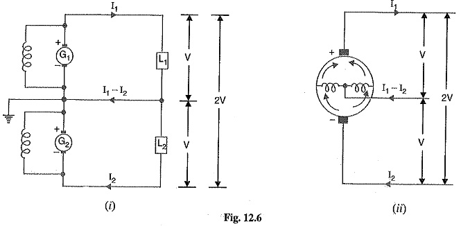
2. 3-wire D.C. Generator: The above method is costly on account of the necessity of two gen For this reason, 3-wire d.c. generator was developed as shown in Fig. 12.6 (ii). It consists of a standard 2-wire machine with one or two coils of high reactance and low resistance, connected permanently to diametrically opposite points of the armature winding. The neutral wire is obtained from the common point as shown.
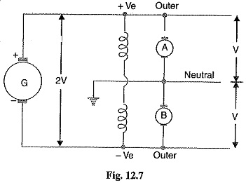
3. Balancer set: The 3-wire system can be obtained from 2-wire d.c. system by the use of balancer set as shown in Fig. 12.7. G is the main 2-wire d.c. generator and supplies power to the whole system. The balancer set consists of two identical d.c shunt machines A and B coupled mechanically with their armatures and field windings joined in series across the outers. The junction of their armatures is earthed and neutral wire is taken out from here. The balancer set has the additional advantage that it maintains the potential difference on two sides of neutral equal to each other.