Potential Dividers for Impulse Voltage Measurements:
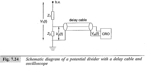
Potential or voltage dividers for high voltage Impulse Voltage Measurements, high frequency a.c. measurements, or for fast rising transient voltage measurements are usually either resistive or capacitive or mixed element type. The low voltage arm of the divider is usually connected to a fast recording oscillograph or a peak reading instrument through a delay cable. A schematic diagram of a potential divider with its terminating equipment is given in Fig. 7.24. Z1 is usually a resistor or a series of resistors in case of a resistance potential divider, or a single or a number of capacitors in case of a capacitance divider.
It can also be a combination of both resistors and capacitors. Z2 will be a resistor or a capacitor or an R-C impedance depending upon the type of the divider. Each element in the divider, in case of high voltage dividers, has a self-resistance or capacitance. In addition, the resistive elements have residual inductances, a terminal stray capacitance to ground, and terminal to terminal capacitances.
The lumped circuits equivalent of a resistive element is already shown in Fig. 7.8 and shown in Fig. 7.9a. A capacitance potential divider also has the same equivalent circuit as in Fig. 7.8a, where Cs will be the capacitance of each elemental capacitor, Cg will be the terminal capacitance to ground, and R will be the equivalent leakage resistance and resistance due to dielectric loss in the element. When a step or fast rising voltage is applied at the high voltage terminal, the voltage developed across the element Z2 will not have the true waveform as that of the applied voltage. The cable can also introduce distortion in the waveshape. The following elements mainly constitute the different errors in the measurements:
(i) Residual inductance in the elements;
(ii) Stray capacitance occurring
- between the elements,
- from sections and terminals of the elements to ground, and
- from the high voltage lead to the elements or sections;
(iii) The impedance errors due to
- connecting leads between the divider and the test objects, and
- ground return leads and extraneous current in ground leads; and
(iv) parasitic oscillations due to lead and cable, inductances and capacitance of high voltage terminal to ground.
The effect to residual and lead inductances becomes pronounced when fast rising Impulse Voltage Measurements of less than one microsecond are to be measured. The residual inductances damp and slow down the fast rising pulses. Secondly, the layout of the test objects, the Impulse Voltage Measurements generator, and the ground leads also require special attention to minimize recording errors.
Resistance Potential Divider:
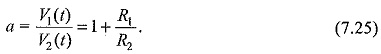
A simple resistance potential divider consists of two resistances R1 and R2 in series (R1 > > R2) (see Fig. 7.25). The attenuation factor of the divider or the voltage ratio is given by
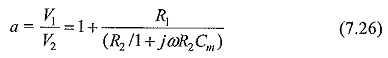
The divider element R2, in practice; is connected through the coaxial cable to the oscilloscope. The cable will generally have a surge impedance Z0 and this will come in parallel with the oscilloScope input impedance (Rm,Cm). Rm will generally be greater than one megaohm and Cm may be 10 to 50 picofarads. For high frequency and Impulse Voltage Measurements (since they also contain high frequency fundamental and harmonics), the ratio in the frequency domain will be given by
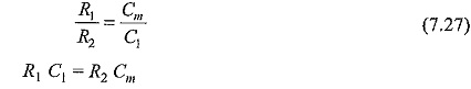
This compensation is used for the construction of high voltage dividers and probes used with oscilloscopes. Usually, probes are made with adjustable values of Cm so that the value of Cm can include any stray capacitance including that of a cable, etc. A typical high voltage probe with a four nanosecond rise time rated for 40 kV (peak) has an input impedance of 100 MΩ in parallel with 2.7 pF.
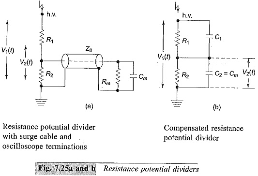
The output waveforms of a compensated divider are shown in Fig. 7.25c with over and under compensation for a square wave input. In Fig. 7.25c (i) is shown the wavfonn of an R-C divider when C1 is too large or overcompensated, while in Fig. 7.25c (iii) is shown the waveform when C1 is small or undercompensated.
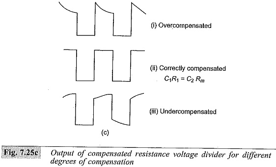
For the exponential slope or for the rising portion of the wave, the time constant τ = [R1R2/(R1 + R2)](C1 + Cm). This will be too large when the value of C1 is greater than that required for correct compensation, i.e. R1 C1 = R2Cm and hence an overshoot with an exponential decay occurs as shown in Fig. 7.25c (i). For undercompensation, the charging time is too high and as such an exponential rise occurs as shown in Fig. 7.25c (iii). The schematic circuit of a compensated oscilloscope probe is shown in Fig. 7,26.
Potential Dividers Used for High Voltage Impulse Measurements
In a resistance potential divider, R1 and R2 are considered as resistors of small dimensions in the previous section. For voltages above 100 kV, R1 is no longer small in dimension and is usually made of a number of sections. Hence the divider is no longer a small resistor of lumped parameters, but has to be considered as an equivalent distributed network with its terminal to ground capacitances and inter-sectional series capacitances as shown in Fig. 7.27. The total series resistance R1 is made of n resistors of value R′1 and R = nR′1.Cg is the terminal to ground capacitance of each of the resistor elements and Cs is the capacitance
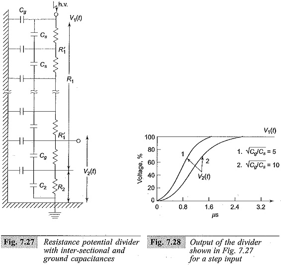
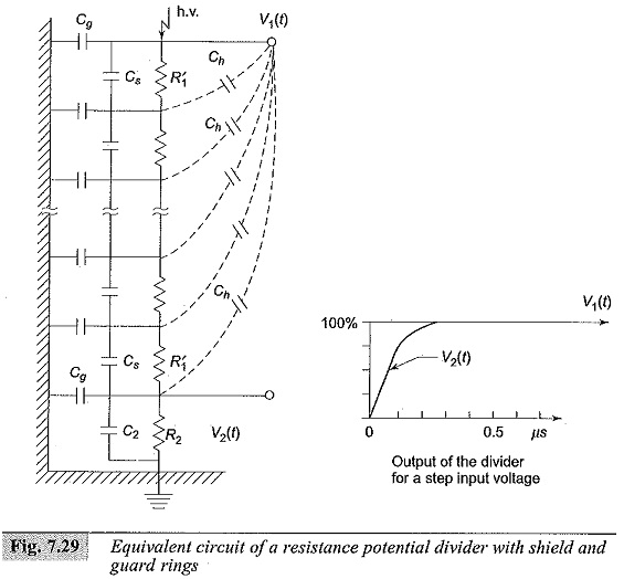
between the terminals of each section. The inductance of each element (L′1) is not shown in the figure as it is usually small compared to the other elements (i.e. R′1,Cs and Cg). This This type of divider produces a non-linear voltage distribution along its length and also acts like an R-C filter for applied voltages. The output of such divider for various values of Cg/Cs ratio is shown in Fig. 7.28 for a step input. By arranging guard rings at various elemental points, the equivalent circuit can be modified as shown Fig. 7.29 in next page, where Ch, represents the stray capacitance introduced between the high voltage lead and the guard elements. This reduces the distortion introduced by the original divider (Plate 5).