Mole Bridge for Low Frequency Measurements:
The bridge that is usually used for low frequency measurements is the Mole Bridge whose schematic diagram is shown in Fig. 9.10. This is primarily devised to measure the dispersion in insulation of installed equipment and gives a reliable measure of the moisture content in the insulation. It is well known that dielectric dispersion increases rapidly with decrease in frequency and hence a more sensitive measurement is obtained at low frequencies.
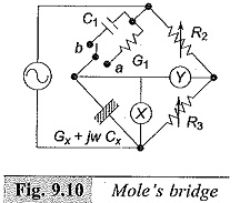
The bridge shown in Fig. 9.10 does not have the conventional balancing system. A cathode ray oscillograph (CRO) is used as the null indicator and the bridge is said to be balanced when the Y plate voltage Vy is in quadrature with X plate voltage Vx. Thus, with the switch in position ‘a’ balance occurs when
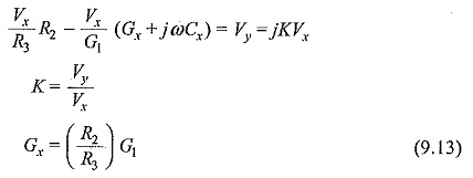
The bridge can be made direct reading in terms of G. Similarly, balance is obtained with the switch in position b when
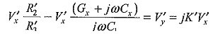
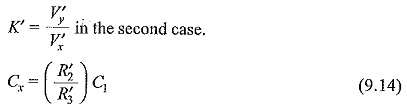
R′2 and R′3 are new values of the ratio arms R2 and R3. By fixing the ratio of R2 and R3, the bridge may be made direct reading for Cx also in terms of C1.
Usually, the bridge employs the ratio arms with a ratio range of 10 : 1 to 1 : 10, capacitance in the range 10 pF to 1.0 μF and conductance in the range 10-10 to 10-6 Siemens (mhos). Oscillators (the source voltages) operate in the frequency range of 0.05 Hz to 100 Hz.