Instrumentation Amplifier Circuit:
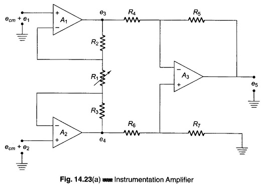
The schematic diagram of an Instrumentation Amplifier Circuit constructed with dc opamps and consisting of general features is shown in Fig. 14.23 (a).
Many of the input specifications of the opamps employed directly determine the input specification of the Instrumentation Amplifier.
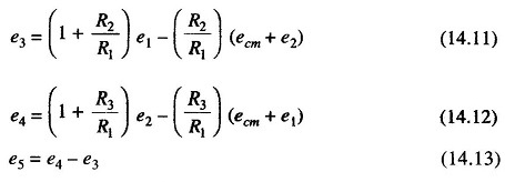
An analysis of the circuit of Fig. 14.23 (a) gives the following equations.
Let
![]()
Therefore,
where
- ecm + e1 is the input to amplifier A1.
and
- ecm + e2 is the input to amplifier A2
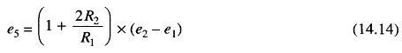
If R2 = R3, the output voltage is given by
The input amplifiers A1 and A2 act as input buffers with unity gain for common mode signals ecm and with a gain of (1 + 2R2/R1) for differential signals.
A high input impedance is ensured by the non-inverting configuration in which they operate. The common mode (CM) rejection is achieved by the following stage which is connected as a differential amplifier. The optimum common mode rejection can be obtained by adjusting R6 or R7 ensuring that R5/R4 = R7/R6.
The amplifier A3 can also be made to have some nominal gain for the whole amplifier by an appropriate selection or R4, R5, R6, and R7.
The drift errors of the second stage add to the product of the drift errors of the first amplifier and first stage gain. Hence, it is necessary that the gain in the first stage be enough to prevent the overall drift performance from being significantly affected by the drift in the second stage. The drift problem of Instrumentation Amplifiers can be improved if amplifiers A1 and A2 have offset voltages which tends to track the temperature.
The gain of an instrumentation amplifier can be varied by changing R1 alone. A high gain accuracy can be obtained by using precision metal film resistors for all the resistances.
Because of the large negative feedback used, the amplifier has good linearity, typically about 0.01% for a gain less than 10. The output impedance is also low, being in the range of milli ohms.
The input bias current of the Instrumentation Amplifier Circuit is determined by that of the amplifiers A1 and A2.
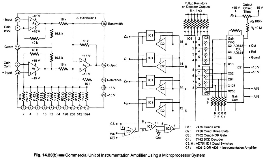
Figure 14.23 (b) shows a commercial unit of an instrumentation amplifier together with a circuit to program it with a microprocessor system.