Harmonic Distortion Analyzer:
A Harmonic Distortion Analyzer measures the total harmonic power present in the test wave rather than the distortion caused by each component. The simplest method is to suppress the fundamental frequency by means of a high pass filter whose cut off frequency is a little above the fundamental frequency. This high pass allows only the harmonics to pass and the total harmonic distortion can then be measured. Other types of Harmonic Distortion Analyzer based on fundamental suppression are as follows.
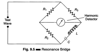
1. Employing a Resonance Bridge:
The bridge shown in Fig. 9.5 is balanced for the fundamental frequency, i.e. L and C are tuned to the fundamental frequency. The bridge is unbalanced for the harmonics, i.e. only harmonic power will be available at the output terminal and can be measured. If the fundamental frequency is changed, the bridge must be balanced again. If L and C are fixed components, then this method is suitable only when the test wave has a fixed frequency. Indicators can be thermocouples or square law VTVMs. This indicates the rms value of all harmonics. When a continuous adjustment of the fundamental frequency is desired, a Wien bridge arrangement is used as shown in Fig. 9.6.
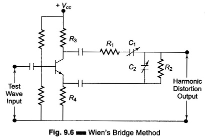
2. Wien’s Bridge Method:
The bridge is balanced for the fundamental frequency. The fundamental energy is dissipated in the bridge circuit elements. Only the harmonic components reach the output terminals. The harmonic distortion output can then be measured with a meter. For balance at the fundamental frequency, C1 = C2 = C, R1 = R2 = R, R3 = 2R4.
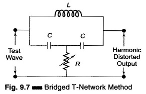
3. Bridged T-Network Method:
Referring to Fig. 9.7 the, L and C’s are tuned to the fundamental frequency, and R is adjusted to bypass fundamental frequency. The tank circuit being tuned to the fundamental frequency, the fundamental energy will circulate in the tank and is bypassed by the resistance. Only harmonic components will reach the output terminals and the distorted output can be measured by the meter. The Q of the resonant circuit must be at least 3-5.
One way of using a bridge T-network is given in Fig. 9.8.
The switch S is first connected to point A so that the attenuator is excluded and the bridge T-network is adjusted for full suppression of the fundamental frequency, i.e. minimum output. Minimum output indicates that the bridged T-network is tuned to the fundamental frequency and that the fundamental frequency is fully suppressed.
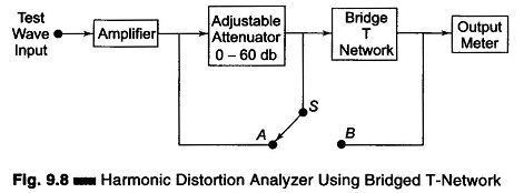
The switch is next connected to terminal B, i.e. the bridged T-network is excluded. Attenuation is adjusted until the same reading is obtained on the meter. The attenuator reading indicates the total rms distortion. Distortion measurement can also be obtained by means of a wave analyzer, knowing the amplitude and the frequency of each component, the Harmonic Distortion Analyzer can be calculated. However, distortion meters based on fundamental suppression are simpler to design and less expensive than wave analyzers. The disadvantage is that they give only the total distortion and not the amplitude of individual distortion components.