TV Video Waveform:
Blanking – TV Video Waveform voltage is limited to certain amplitude limits. Thus, for example, the white level corresponds to 12.5 percent (±2.5 percent) modulation of the carrier, and the black level corresponds to approximately 67.5 percent modulation. Thus, at some point along the video amplifier chain, the voltage may vary between 1.25 and 6.75 V, depending on the relative brightness of the picture at that instant. The darker the picture, the higher will be the voltage, within those limits. At the receiver, the picture tube is biased to ensure that a received video voltage corresponding to 12.5 percent modulation yields whiteness at that particular point on the screen, and an equivalent arrangement is made for the black level. Besides, set owners are supplied with brightness and contrast controls, to make final adjustments as they think fit. Note that the lowest 12.5 percent of the modulation range (the whiter-than-white region) is not used, to minimise the effects of noise.
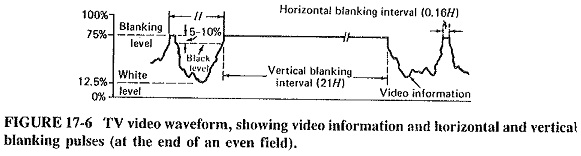
When the picture is blanked out, before the vertical or horizontal retrace, a pulse of suitable amplitude and duration is added to the TV Video Waveform voltage, at the correct instant of time. Video superimposed on top of this pulse is clipped, the pulses are clamped, and the result is video with blanking, shown in Figure 17-6. As indicated, the blanking level corresponds to 75 percent (±2.5 percent) of maximum modulation. The black level is actually defined relatively rather than absolutely. It is 5 to 10 percent below the blanking level, as shown in Figure 17-6. If in a given transmission the blanking level is exactly 75 percent, then the black level will be about 7.5 percent below this, i.e., approximately 67.5 percent as previously stated. At the video point mentioned previously, we thus have white at 1.25 V, black at about 6.75 V and the blanking level at 7.5 V.
The difference between the blanking level and the black level is known as the Setup Interval. This is made of sufficient amplitude to ensure that the black level cannot possibly reach above the blanking level. If it did, it would intrude into the region devoted exclusively to sync pulses, and it might interfere with the synchronisation of the scanning generators.
Synchronising Pulses:
As shown in Figure 17-7, the procedure for inserting synchronising pulses is fundamentally the same as used in blanking pulse insertion. Horizontal and vertical pulses are added appropriately on top of the blanking pulses, and the resulting TV Video Waveform is again clipped and clamped. It is seen that the tips of horizontal and vertical synchronising pulses reach a level that corresponds to 100 percent modulation of the picture carrier. At the hypothetical video point mentioned previously, we may thus have video between 1.25 and 6.75 V, the blanking level at 7.5 V and the sync pulse tips at 10 V. The overall arrangement may be thought of as a kind of voltage-division multiplex.
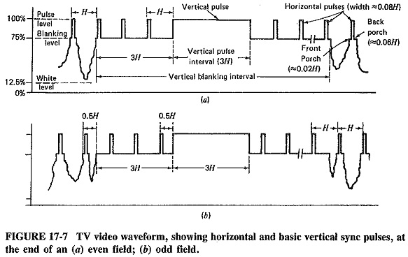
It should be noted that the horizontal sync information is extracted from the overall TV Video Waveform by differentiation. Pulses corresponding to the differentiated leading edges of sync pulses are actually used to synchronise the horizontal scanning oscillator. This is the reason why, in Figures 17-6 to 17-8, all time intervals are shown between pulse leading edges. Receivers often use monostable-type circuits to generate horizontal scan, so that a pulse is required to initiate each and every cycle of horizontal oscillation in the receiver. With these points in mind, it should be noted that there are two things terribly wrong with the sync pulses shown in Figure 17-7.
The first and more obvious shortcoming of the TV Video Waveform shown may be examined with the aid of Figure 17-7a. After the start of the vertical blanking period, the leading edges of the three horizontal sync pulses and the vertical sync pulse shown will trigger the horizontal oscillator in the receiver. There are no leading edges for a time of 3H after that, as shown, so that the receiver horizontal oscillator will either lose sync or stop oscillating, depending on the design.
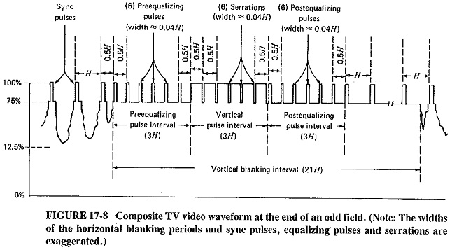
It is obvious that three leading edges are required during this 3H-period. By far the easiest way of providing these leading edges is to cut slots in the vertical sync pulse. The beginning of each slot has no effect, but the end of each provides the desired leading edge. These slots are known as serrations. They have widths of 0.04H each and are shown exaggerated in Figure 17-8 (to ensure that they are visible). Note that, at the end of an even field, serrations 2, 4 and 6 or, to be precise, the leading edges following these three serrations, are actually used to trigger the horizontal oscillator in the receiver.
The situation after an odd field is even worse. As expected, and as shown in Figure 17-7b the vertical blanking period at the end of an odd field begins midway through a horizontal line. Looking further along this TV Video Waveform, we see that the leading edge of the vertical sync pulse comes at the wrong time to provide synchronisation for the horizontal oscillator. The obvious answer is to have a serration such that the leading edge following it occurs at time H after the leading edge of the last horizontal sync pulse. Two more serrations will be required, at H intervals after the first one. In fact, this is the reason for the existence of the first, third and fifth serrations in Figure 17-8. The overall effect, as shown, is that there are six serrations altogether, at 0.5H intervals from one another.
Note that the leading edges which now occur midway through horizontal lines do no harm. All leading edges are used sometime, either at the end of an even field or at the end of an odd one. Those that are not used in a particular instance come at a time when they cannot trigger the horizontal waveform, and they are ignored.
We must now turn to the second shortcoming of the waveforms of Figure 17-7. First, it must be mentioned that synchronisation is obtained in the receiver from vertical sync pulses by integration. The integrator produces a small output when it receives horizontal sync pulses, and a much larger output from vertical sync pulses, because their energy content is much higher. What happens is that as a result of receiving a vertical pulse, the output level from the integrator eventually rises enough to cause triggering of the vertical oscillator in the receiver.
We must note at this stage that the residual charge on this integrating circuit will be different at the start of the vertical sync pulses in Figure 17-7a and 17-7b. In the former, the vertical sync pulse begins a time H after the last horizontal pulse. In the latter, this difference is only 0.5H, so that a higher charge will exist across the Capacitor in the integrating circuit. The equalising pulses shown in the composite TV Video Waveform of Figure 17-8 take care of this situation. It is seen that the period immediately preceding each vertical pulse is the same, regardless of whether this pulse follows an even or an odd field. Charge is equalised and jitter is prevented.
Observant students will have noted that the vertical sync pulse begins 3H after the start of the vertical blanking period, although Figure 17-5 showed the vertical retrace beginning four lines (i.e., 4H) after the start of vertical blanking. The discrepancy can now be explained. It is simply caused by the integrating circuit taking a time approximately equal to H, from the moment when the vertical sync pulse begins to the instant when its output is sufficient to trigger the vertical retrace.
Summary:
It is seen that the provision of blanking and synchronising pulses, to ensure that TV receivers scan correctly, is a very involved process. It is also seen how important it is to have adequate television transmission standards.
All systems have the same general principles in common. In each, blanking is applied before, and removed after, synchronising pulses. A front porch precedes a horizontal sync pulse, and a back porch follows such a pulse, in all the systems. All systems have equalising pulses, though not necessarily the same number as in the FCC system. In all cases serrations are used to provide horizontal sync during vertical pulses, with some minor differences as applicable. The width of a vertical pulse in the CCIR system is 2.5H, and the H itself is different from H in the American system.
Three final points should now be mentioned. The first is that many people refer to a set of six vertical sync pulses, which this section has been consistent in referring to a single pulse with six serrations. The difference in terminology is not very significant, as long as the user explains what is meant. Second, it is a moot point whether the vertical pulse has five or six serrations. This section has referred to the no-pulse region between the trailing edge of the vertical pulse and the first postequalizing pulse as a serration. This is done because, if there were no serrations, this period would be occupied by the final portion of the vertical sync pulse, whose trailing edge has now been cut into. Other sources do not consider this as a serration, but again the point is not significant, as long as the terms are adequately defined.
The third item is related to the fact that the one crystal-controlled source is used for all the various pulses transmitted. It operates at 31,500 Hz; this is twice the horizontal frequency and is also the repetition rate of the equalising pulses and serrations.
The horizontal frequency is obtained by dividing 31,500 Hz by 2. Similarly, the 60-Hz field frequency is achieved by dividing 31,000 Hz by 525 (i.e., 7 x 5 x 5 x 3). This point acquires added significance in color television.